Request a Quote
Share your product list, technical ratings, quantity and delivery destination.
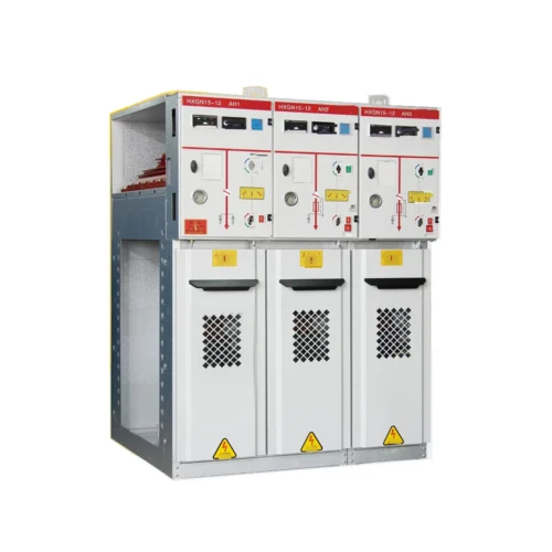
A 12 kV, 630 A ring main unit family using air or nitrogen insulation with vacuum interruption. Select the feeder arrangement, protection and gas specification together, then coordinate top or side expansion with the cable layout and switchroom.

A 12 kV, 630 A ring main unit family using air or nitrogen insulation with vacuum interruption. Select the feeder arrangement, protection and gas specification together, then coordinate top or side expansion with the cable layout and switchroom.
HLHB-12 uses air or nitrogen insulation with vacuum interruption. Circuit-breaker, cable-connection and PT cabinets are combined around the project feeder scheme. The order identifies the insulation gas and the top or side expansion arrangement. Protection, monitoring and cable interfaces are specified for the selected lineup.
| Electrical parameter | Specification |
|---|---|
| Product family | HLHB-12 gas-insulated ring main unit |
| Rated voltage | 12 kV |
| Rated current | 630 A |
| Rated frequency | 50 Hz |
| Insulation medium | Pure air or nitrogen, as specified for the selected unit |
| Arc interruption | Vacuum interrupter |
| Circuit-breaker short-circuit breaking rating | 20 kA; selected breaker configuration |
| Main-circuit short-time withstand | 20 kA for 3 s |
| Main-circuit peak withstand | 50 kA |
| Power-frequency withstand, 1 min | 42 kV phase-to-earth / phase-to-phase; confirm isolation-gap requirements |
| Lightning impulse withstand, peak | 75 kV phase-to-earth / phase-to-phase; confirm isolation-gap requirements |
| Reference gas pressure | 0.02 MPa gauge; confirm gas and filling specification |
| Reference protection degrees | IP67 gas compartment; IP4X outer enclosure; not one combined rating |
Confirm the selected assembly, component ratings and verification documents. Family options do not describe every supplied configuration.
Select the electrical arrangement and interfaces for the intended duty.
| Selection item | Specification / requirement |
|---|---|
| Circuit-breaker cabinet | Vacuum-breaker feeder with selected protection |
| Cable-connection cabinet | Cable interface defined by the single-line diagram |
| PT cabinet | Voltage measurement arrangement as specified |
| Expansion direction | Top or side; coordinate interfaces before ordering |
| Control and sensing | Relay, instrument, CT and communication scope by project |
The selected order code and approved drawings define the delivered equipment.
Apply the breaking rating only to the selected vacuum-breaker circuit. Isolation and earthing functions must follow the approved interlocking scheme.
Confirm pressure indication, alarm settings and maintenance instructions for the specified gas mixture.
Provide fault level, earthing system and feeder duties before selecting CTs, relays and settings.
Functional overview only. Qualified personnel must follow the approved isolation procedures and supplied operating instructions.
Define the equipment duty and interfaces before requesting the project configuration.
| Configuration item | Purpose | Define for your project |
|---|---|---|
| Feeder duty | Define protection and switching | Single-line diagram and fault-current schedule |
| Gas system | Define insulation arrangement | Gas composition, filling pressure and supporting documents |
| Expansion | Coordinate adjacent panels | Top or side connection and future extension |
| Cable interface | Avoid installation conflicts | Cable list, termination details and entry direction |
| Control package | Coordinate monitoring | Relay, CT, auxiliary supply and communications |
Final components and scope of supply are defined in the project quotation.
| Interface | Reference / requirement | Selection note |
|---|---|---|
| Top-expansion breaker / cable cabinet | 420 x 850 x 1950 mm | Width x depth x height, reference only |
| Top-expansion PT cabinet | 600 x 850 x 1950 mm | Reference body dimensions |
| Side-expansion breaker / cable cabinet | 420 x 850 x 2000 mm | Reference body dimensions |
| Side-expansion PT cabinet | 600 x 850 x 2000 mm | Reference body dimensions |
| Installation envelope | Use the approved arrangement drawing | Outline shows projections beyond nominal body depth |
Reference dimensions support layout planning. Use the approved drawing for installation.

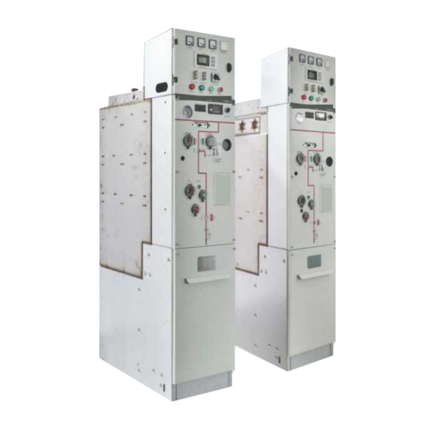
HLHB-12 outline
Confirm top or side expansion, future extension and busbar interfaces on the approved arrangement.
Submit cable count, termination type and bending requirements before fixing the cable-room layout.
Verify nameplate, gas specification, interlocks and supplied inspection records before energization.
| Condition | Requirement / project input |
|---|---|
| Reference ambient | -40 to +50 C; confirm the selected design and duty |
| Reference altitude | Up to 4000 m in the source conditions; confirm insulation and derating |
| Average relative humidity | Daily up to 95%; monthly up to 90% |
| Installation environment | Confirm indoor or enclosed installation, condensation and ventilation |
| Special conditions | State pollution, corrosion and seismic requirements for review |
Provide any conditions outside the stated range before ordering. Final suitability requires project-specific confirmation.
Configure breaker and cable-connection functions around the ring-network diagram.
Identify air or nitrogen in the equipment schedule and request the matching technical documents.
Select top or side extension and coordinate the initial cable and room layout with future sections.
A planning example for specifying HLHB-12 feeder functions, gas composition and extension interfaces together.
Provide fault duty, protection requirements and any PT or metering functions.
Identify the required insulation gas and the pressure-indication and alarm requirements.
Select top or side expansion and check its dimensions, cable layout and room clearances.
Production follows the approved drawings, the applicable product standards and the agreed inspection plan.
We can adjust the configuration for your operating environment and provide neutral packaging or your logo. Send the site conditions and branding requirements with your enquiry.
Incoming components, production work and finished units are checked against the requirements for the ordered configuration.
Incoming materials and components are checked against the approved specifications before production.
Assemblies and semi-finished components are inspected at the relevant production stages.
Finished equipment and release records are checked against the approved order requirements.
Factory acceptance testing (FAT). Every unit undergoes FAT before packing. Test items and acceptance criteria follow the product and approved configuration. FAT reports and packing inspection photos accompany the shipment. Factory attendance, video witnessing or independent inspection can be arranged with an agreed scope and schedule.
Send your required ratings, installation conditions and quantity. We will confirm the configuration and documents for your quotation.
The selected gas composition, circuit functions and equipment ratings.
Top or side connections, cable layout and foundation.
Applicable assembly reports, gas records and factory tests.
No. The technical schedule lists pure air or nitrogen. Specify the actual gas in the order and obtain the corresponding documents; do not infer a verified environmental certification from the label.
No. The reference distinguishes an IP67 gas compartment from an IP4X outer enclosure. Confirm the selected assembly and installation environment.
No. The 20 kA breaking value applies to the listed circuit-breaker configuration. Cable, isolation and earthing functions have their own duties.
Do not assume so. The listed heights and interfaces differ; use an approved lineup and connection drawing.
Send the single-line diagram, feeder duties, fault level, gas requirement, protection schedule, cable information and available space.