Request a Quote
Share your product list, technical ratings, quantity and delivery destination.
APPLICATIONS / MINING
HJD supplies MV switchgear, transformers and LV distribution cabinets for surface mine facilities, crushing plants and pump stations. Build the equipment package around your load schedule and site layout.
Crushing & conveying / Remote pumps / Site expansion
01 / SUPPLY ARRANGEMENT
Cable routes, starting duty and isolation requirements shape the supply layout.
1
Motor starting can cause a voltage dip at the crusher, conveyor and other connected loads. Check the supply, transformer and feeder together, using the motor’s starting method and duty.
Send motor ratings, starting methods and the single-line diagram. HJD can then match the switchgear, transformer and LV feeder interfaces to the project specification.
2
A long LV cable run can make voltage drop and cable size drive the installation cost. Compare it with extending the MV network and placing a transformer closer to the pump station or process area.
Mark cable lengths, elevation changes, load ratings and available equipment locations on the site plan. Use the selected layout to define the MV feeder, transformer and local LV distribution package.
3
Before adding another process line, recheck loading, fault levels and protection coordination. Identify which feeders must remain available when a section is maintained, then check spare ways, busbar interfaces and upstream capacity.
Give HJD the existing lineup drawings and future load schedule. Agree the connection points, protection interfaces and space for the new equipment before manufacture.
02 / COMPARE OPTIONS
EXISTING DISTRIBUTION POINT
Supply the new pump or process load from the existing transformer and LV board.
LOCAL TRANSFORMER POINT
Extend an MV feeder to a transformer and LV board near the remote process area.
03 / EQUIPMENT & INTERFACES
For the electrical-room package shown, specify dust control, ventilation, ambient temperature and altitude before selecting the configuration.
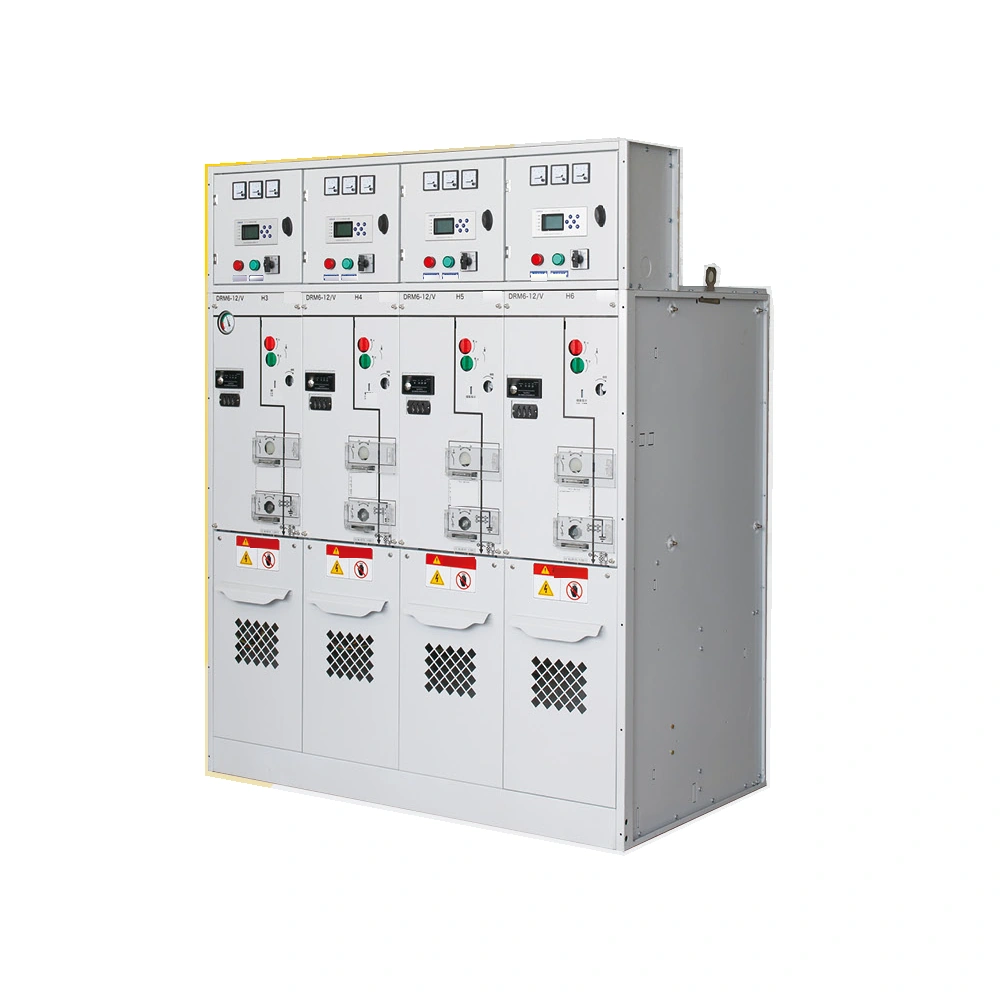
INCOMING & FEEDER SWITCHING
DRM6-12 ring main unit
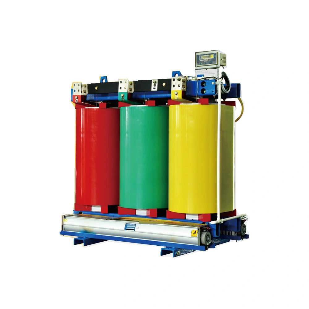
VOLTAGE & LOAD MATCHING
SC(B)13 dry-type series
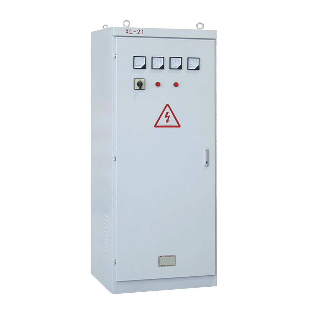
PROCESS & SITE SERVICE FEEDERS
XL-21 distribution series
04 / FAQ
Use the simultaneous load, motor-starting duty and planned expansion, rather than adding motor nameplate ratings alone. Include the supply and load voltages, transformer impedance, drive loads and installation conditions. The project electrical design should check loading and starting voltage drop together.
Compare both arrangements using load power, route length, voltage drop, cable cost and future expansion. Taking MV to a local transformer can shorten the LV runs, but adds equipment, protection and maintenance requirements.
Starting current creates a voltage drop across the supply network, transformer and cables. The size and duration of the dip depend on the source, motor and starting method. Review these together before increasing transformer capacity or changing the starter.
Specify the conditions at the equipment location: airborne dust, water exposure, condensation, temperature and altitude. Use these to select the room or housing, ventilation and equipment ratings. If the location has an explosive atmosphere, its hazardous-area classification becomes a separate equipment requirement.
Check measured demand, transformer and cable capacity, busbar ratings, spare ways and starting duty. Recalculate fault levels and coordinate the added protection. Where the existing lineup cannot be extended, compare a separate transformer and distribution point.
Send the single-line diagram, load list and site plan with cable routes. Include supply voltage, fault level, motor ratings and starting methods, equipment locations and environmental conditions. For an extension, add existing nameplates, lineup drawings, connection photos and the planned shutdown window.
Send your product list, technical ratings, quantity and delivery destination.
