Request a Quote
Share your product list, technical ratings, quantity and delivery destination.
APPLICATIONS / DATA CENTERS
Plan the electrical supply for a new data hall or the next capacity increase. HJD supplies transformers and MV/LV distribution equipment to the project specification.
New facility / Phased growth / Existing-site work
01 / THE SOLUTION
The load schedule and operating arrangement determine the intake capacity, transformer duties and outgoing feeders.
1
IT demand alone does not describe the full facility load. Cooling plant and auxiliary services also need defined supply paths.
Use the load schedule and supply voltage to specify transformer capacity, incoming protection and outgoing feeders. Show UPS and generator connection points on the project diagram.
2
Decide which intake equipment will serve later phases and which transformer and feeder blocks will be added with each data hall.
HJD uses the phase schedule to identify equipment quantities, cable interfaces and space needed for later additions. Check upstream capacity before repeating a power block.
3
Equipment work can affect IT systems and the cooling they depend on. Identify the isolation boundary and any temporary supply before planning the change.
Match new equipment to the existing cables, protection, control power and signals. The site team coordinates switching, functional tests and the restart sequence.
02 / COMPARE THE BUILD SEQUENCE
The choice changes upfront equipment, reserved space and future connection work.
OPTION A
Provide the agreed intake and transformer capacity ahead of later data-hall demand.
OPTION B
Install transformer and distribution blocks as new halls are brought into service.
03 / EQUIPMENT & INTERFACES
Use these families to start the equipment discussion. Match each configuration to the project voltage, fault duty and operating arrangement.
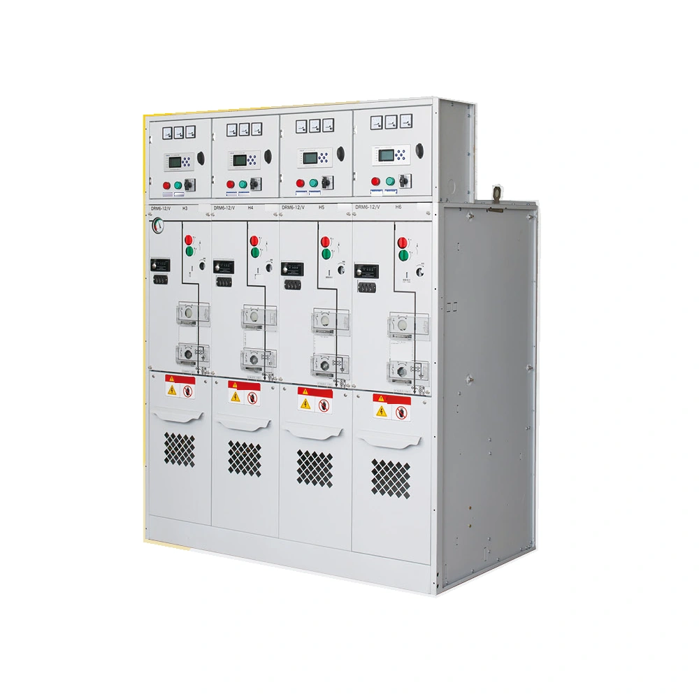
INCOMING & FEEDER SWITCHING
DRM6-12 ring main unit
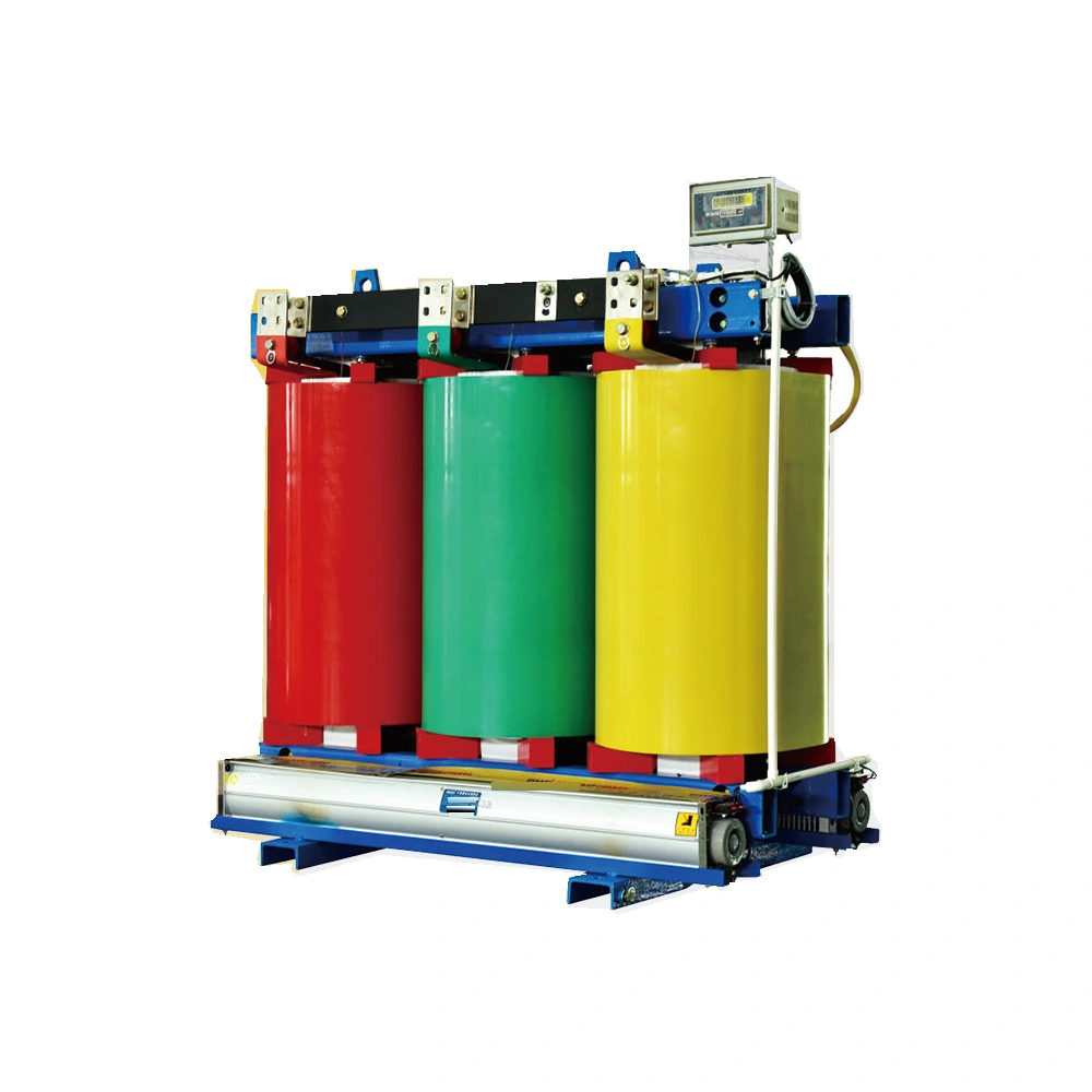
VOLTAGE & LOAD MATCHING
SC(B)13 dry-type series
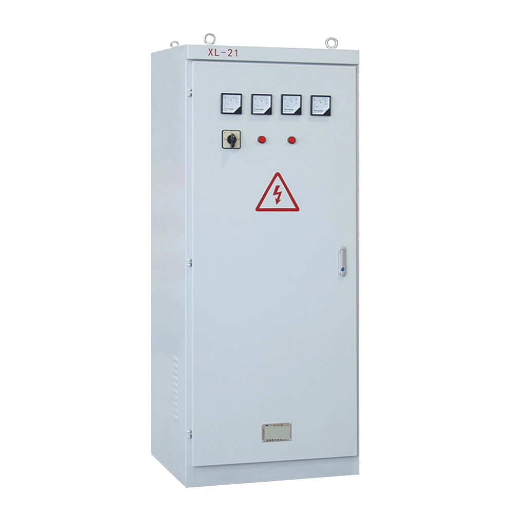
FACILITY DISTRIBUTION CIRCUITS
XL-21 distribution series
04 / FAQ
A facility supply commonly passes through incoming switchgear and transformers before reaching downstream distribution. IT, cooling and auxiliary loads need their own defined paths. The project diagram should show where UPS and generator systems connect and how the paths operate during normal service and maintenance.
Show each supply source, voltage level, transformer and switchgear section, then identify the IT, cooling and auxiliary feeders. Mark UPS and generator connections, isolation points and any normal-open links. For a phased project, distinguish installed equipment from the connection points reserved for later work.
Start with the load schedule for each phase and the required primary and secondary voltages. Compare capacity, impedance, installation space, insulation, cooling and monitoring requirements. Review the transformer with its switching and protection equipment, including the expected operating and switching conditions.
It switches and isolates circuits and provides the protection and metering assigned to that part of the system. Specify fault duty, feeder arrangement, protection coordination, control supply and required interlocks. The operating arrangement determines which sections must remain supplied while another section is isolated.
Check the available utility capacity and the rating of each existing supply path. Add the new IT, cooling and auxiliary loads to the phase schedule. Then review fault duty, protection, equipment space, cable routes and the planned connection window. Temporary power must be allocated to the loads it can actually carry.
The available supply paths, isolation arrangement and temporary-power capacity determine what can stay in service. Define the loads affected by each switching step and the checks required before restart. Stanford planned a facility shutdown for its maintenance work; NERSC published service reductions for its capacity upgrade.
Send your product list, technical ratings, quantity and delivery destination.
