Request a Quote
Share your product list, technical ratings, quantity and delivery destination.
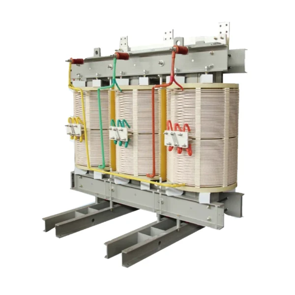
An open-ventilated dry-type transformer family with vacuum-pressure-impregnated insulation. Select the voltage ratio, capacity, enclosure and cooling requirements separately from cast-resin and low-voltage SG products. The order-specific electrical schedule resolves the final configuration.

An open-ventilated dry-type transformer family with vacuum-pressure-impregnated insulation. Select the voltage ratio, capacity, enclosure and cooling requirements separately from cast-resin and low-voltage SG products. The order-specific electrical schedule resolves the final configuration.
SG(B)10 uses vacuum-pressure impregnation of the winding insulation in an open-ventilated dry-type design. Winding form, cooling and enclosure are selected for the required load and installation. Confirm the complete HV/LV ratio, impedance, connection group and loss schedule for the ordered unit. The family designation alone does not establish those values.
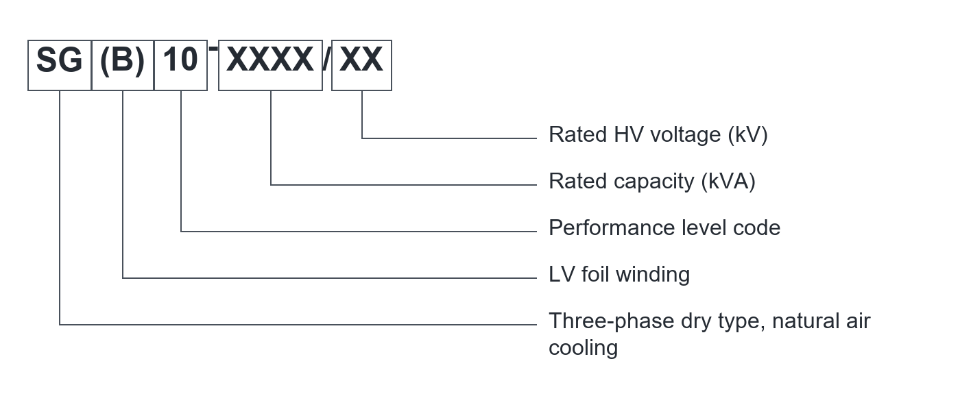
Capacity and HV voltage are specified with the order.
| Electrical parameter | Specification |
|---|---|
| Product family | SG(B)10 open-ventilated dry-type transformer |
| Impregnation process | Vacuum-pressure impregnation, VPI |
| Listed capacity range | 30-2500 kVA; select the required duty |
| Family voltage-class heading | 6 kV / 10 kV; verify the selected voltage ratio |
| Actual HV / LV ratio | Order-specific confirmation required; mixed source table not used as a guaranteed ratio |
| Reference frequency | 50 Hz |
| Insulation system | Class H, 180 C system |
| Main insulation material | Source describes 220 C-class aramid paper; not a 220 C complete-system rating |
| Reference winding temperature rise | 125 K; confirm the selected design and test basis |
| Winding form | Open-ventilated HV and LV winding arrangements, design-dependent |
| Cooling and enclosure | Specify together for the duty and installation |
| Losses, impedance and vector group | Obtain the matched electrical schedule for the selected rating |
Confirm the selected assembly, component ratings and verification documents. Family options do not describe every supplied configuration.
Select the exact electrical design before using any family reference dimensions or performance data.
| Selection item | Specification / requirement |
|---|---|
| VPI insulation | Vacuum-pressure treatment of the winding insulation |
| HV winding | Disc or layer arrangement according to the design |
| LV winding | Wire or foil arrangement according to the selected capacity |
| Thermal design | Class H system and selected cooling duty |
| Enclosure | Specify protection, ventilation and access separately |
| Monitoring | Confirm temperature indication, alarms and fan-control scope |
The selected order code and approved drawings define the delivered equipment.
Keep ventilation passages clear and match the cooling and temperature-monitoring package to the ordered load duty.
Set primary and secondary protection using the confirmed electrical schedule and project study.
Follow the supplied de-energization, cleaning and inspection instructions; the open winding arrangement does not remove electrical hazards.
Functional overview only. Qualified personnel must follow the approved isolation procedures and supplied operating instructions.
Define the equipment duty and interfaces before requesting the project configuration.
| Configuration item | Purpose | Define for your project |
|---|---|---|
| Electrical duty | Define the actual transformer | kVA, HV/LV ratio, frequency and connection |
| VPI construction | Distinguish from cast resin | Winding design, insulation system and documentation |
| Thermal package | Match site and load | Cooling, temperature rise and monitoring |
| Enclosure and interfaces | Coordinate installation | Protection, ventilation, dimensions and cable connection |
| Verification documents | Confirm the ordered performance | Matched loss, impedance and test schedule |
Final components and scope of supply are defined in the project quotation.
| Interface | Reference / requirement | Selection note |
|---|---|---|
| Main-body reference | Figure 16 shows L, W, H and mounting D | Use the approved drawing for the exact rating |
| Enclosure reference | L1 and H1 denote enclosure-related dimensions | Confirm complete enclosure width and clearance |
| Mounting interface | Track / bolt layout depends on selected capacity | Do not size a foundation from a family photograph |
| Terminations | Confirm HV and LV interfaces on the order drawing | Do not reuse the low-voltage SG drawing |
Reference dimensions support layout planning. Use the approved drawing for installation.
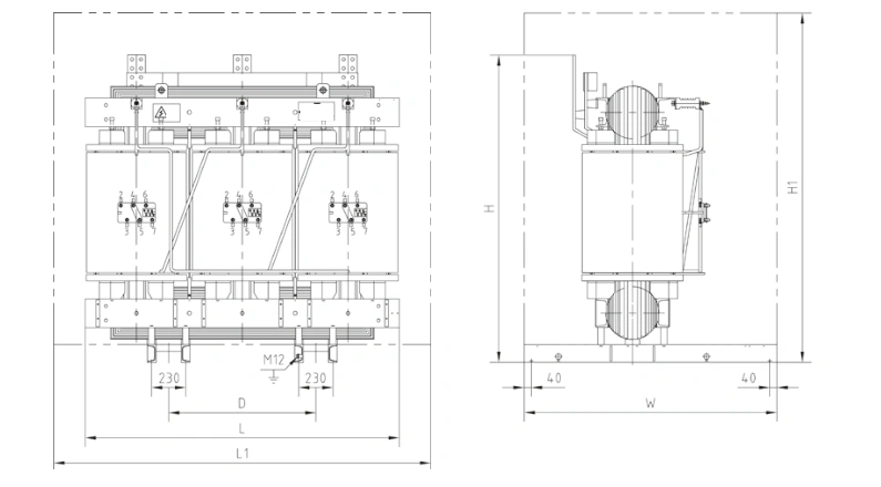
SG(B)10 outline
Confirm room ventilation, equipment access and cable clearances before fixing the layout.
Use the approved mass, lifting points, base dimensions and terminal arrangement for the selected unit.
Check nameplate voltages, connections, tap arrangement and supplied test documents against the approved order.
| Condition | Requirement / project input |
|---|---|
| Reference location | Indoor |
| Reference ambient range | -5 to +40 C |
| Monthly average relative humidity | Up to 90% at 25 C in the source reference |
| Altitude | Confirm for the project; source unit is inconsistent |
| Contamination and condensation | Define site exposure and any enclosure or treatment requirements |
| Operating duty | State continuous load, cyclic load and any overload requirement for assessment |
Provide any conditions outside the stated range before ordering. Final suitability requires project-specific confirmation.
Specify the required electrical duty together with airflow, enclosure and access requirements.
Compare the existing electrical schedule, terminal arrangement and mounting with the proposed unit.
Review the enclosure ventilation, protection and maintenance access with the selected cooling duty.
For a proposed SG(B)10 assembly, confirm the electrical design before fixing the enclosure and ventilation layout.
Agree kVA, HV/LV ratio, frequency, connection group, impedance and losses.
State load duty, site conditions, temperature indication, alarms and fan-control requirements.
Review ventilation passages, access, terminals and the installation footprint against the selected outline.
Production follows the approved drawings, the applicable product standards and the agreed inspection plan.
We can adjust the configuration for your operating environment and provide neutral packaging or your logo. Send the site conditions and branding requirements with your enquiry.
Incoming components, production work and finished units are checked against the requirements for the ordered configuration.
Incoming materials and components are checked against the approved specifications before production.
Assemblies and semi-finished components are inspected at the relevant production stages.
Finished equipment and release records are checked against the approved order requirements.
Factory acceptance testing (FAT). Every unit undergoes FAT before packing. Test items and acceptance criteria follow the product and approved configuration. FAT reports and packing inspection photos accompany the shipment. Factory attendance, video witnessing or independent inspection can be arranged with an agreed scope and schedule.
Send your required ratings, installation conditions and quantity. We will confirm the configuration and documents for your quotation.
Confirmed HV/LV ratio, connection, impedance and loss data.
Selected construction, terminals, ventilation and mounting.
Insulation system, temperature-rise basis and applicable tests.
No. This page covers open-ventilated, vacuum-pressure-impregnated construction. The SC(B) pages cover a separate cast-resin product family.
No. SG(B)10 is a separate family listed under a 6/10 kV-class heading. Use the approved order-specific voltage ratio, not the low-voltage SG schedule.
Not reliably. The family heading and HV/LV entries are inconsistent. Request a corrected electrical schedule before quoting or ordering the voltage ratio.
No. The source describes a 180 C Class H system using higher-temperature-class main insulation material. Confirm the complete thermal design.
Provide kVA, HV and LV voltages, frequency, connection, load duty, site conditions, enclosure, cooling, installation constraints and the required verification documents.