Request a Quote
Share your product list, technical ratings, quantity and delivery destination.
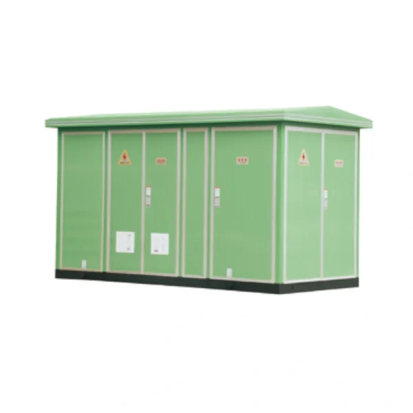
Bring the high-voltage switching, transformer and low-voltage distribution sections into one prefabricated substation. The YB-12 family supports 6 or 10 kV distribution projects with a 0.4 kV low-voltage side; the single-line diagram defines the final assembly.
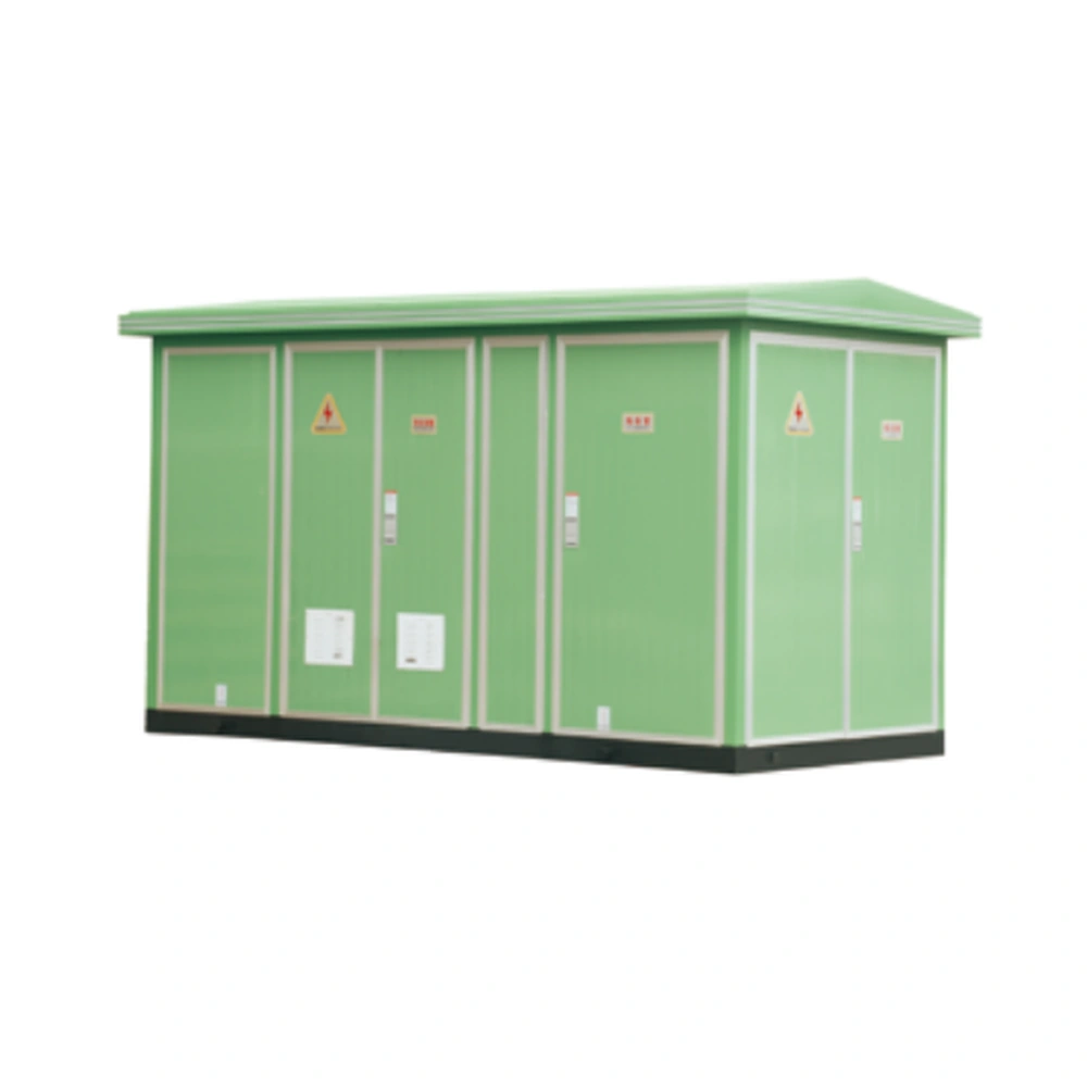
Bring the high-voltage switching, transformer and low-voltage distribution sections into one prefabricated substation. The YB-12 family supports 6 or 10 kV distribution projects with a 0.4 kV low-voltage side; the single-line diagram defines the final assembly.
YB-12 brings the high-voltage, transformer and low-voltage sections into one prefabricated substation. The single-line diagram sets the switching, transformation and outgoing-distribution functions. Transformer rating, feeder equipment and housing arrangement are coordinated together. Access, ventilation, cable entry and foundation details define how the assembly fits the site.
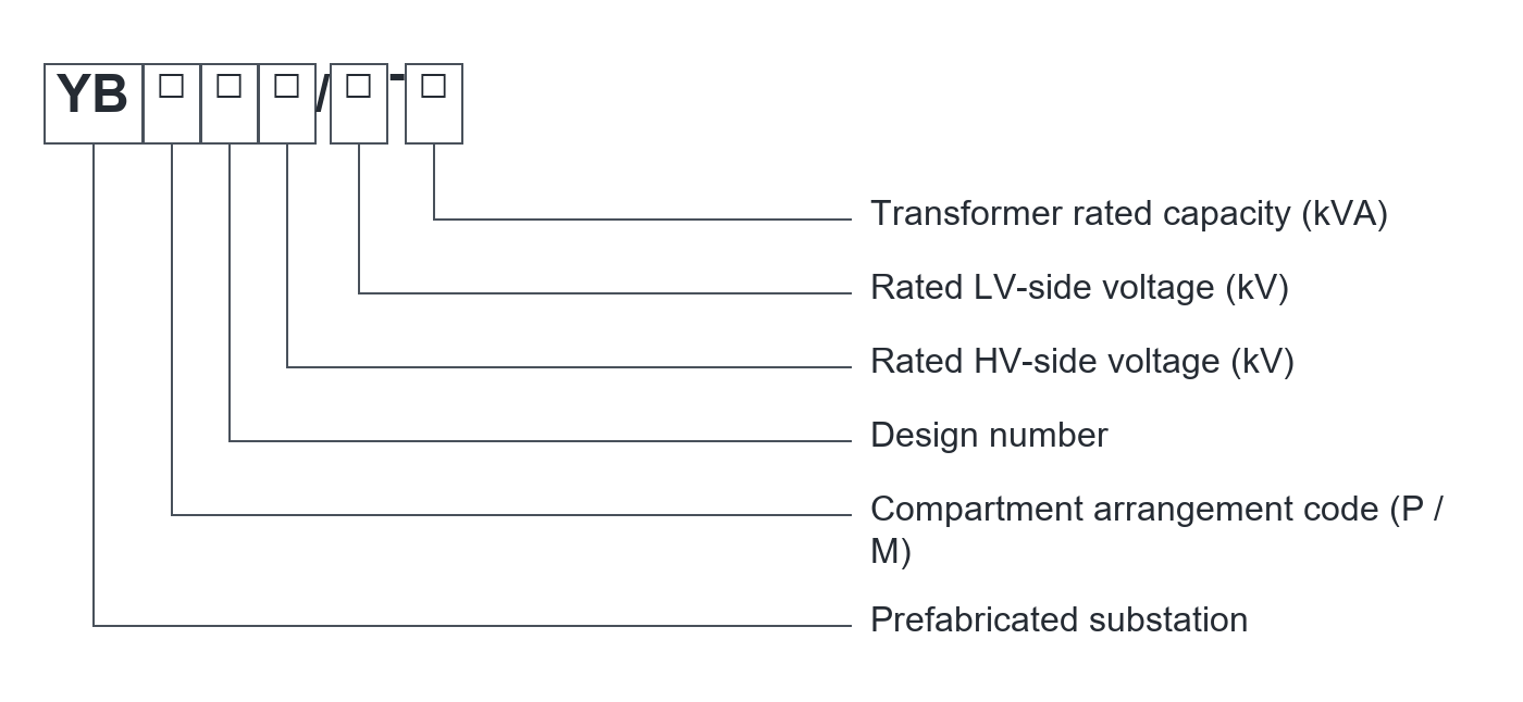
| Electrical parameter | Specification |
|---|---|
| Model family | YB-12; full order code defines the configuration |
| HV system voltage options | 6 kV or 10 kV |
| Transformer voltage options | 6/0.4 kV or 10/0.4 kV |
| Transformer capacity range | 50–1600 kVA; select one project rating |
| HV component current options | 200 / 400 / 630 A, by circuit and device |
| LV distribution current range | 100–3200 A, subject to selected assembly |
| Short-circuit duty | Coordinate the HV device, transformer impedance and LV protection |
| Frequency and insulation schedule | Confirm for the destination network and selected components |
Confirm the selected assembly, component ratings and verification documents. Family options do not describe every supplied configuration.
Match the equipment configuration to the circuit duty and installation interfaces.
| Selection item | Specification / requirement |
|---|---|
| High-voltage section | Define incoming circuit, switching, protection and metering |
| Transformer section | Select rating, voltage ratio, cooling arrangement and losses |
| Low-voltage section | Define main device, outgoing feeders and required metering |
| Housing arrangement | Select access, ventilation, compartment layout and exterior finish |
| Auxiliary systems | Confirm lighting, heaters, controls and auxiliary supply where required |
Confirm the selected order code and component schedule before approval.
Coordinate the selected HV switching device, transformer protection and LV main device with the network study.
Define key interlocks, earthing provisions and access conditions in the approved scheme.
Keep access to terminations, operating mechanisms and ventilation paths clear.
List factory-installed equipment, external cables, civil works and site commissioning in the quotation.
Functional overview only. Qualified personnel must follow the approved isolation procedures and supplied operating instructions.
Define the equipment duty and interfaces before requesting the project configuration.
| Configuration item | Purpose | Define for your project |
|---|---|---|
| HV switching | Connect and isolate the transformer circuit | Device type, feeder arrangement and protection |
| Transformer | Match network voltage to LV loads | kVA, ratio, impedance, losses and vector group |
| LV distribution | Feed and protect outgoing circuits | Current, fault duty and feeder schedule |
| Housing and base | Support equipment and site interfaces | Access, ventilation, cable entries and foundation |
| Verification package | Document the proposed assembly | Applicable requirements and available records |
Final components and scope of supply are defined in the project quotation.
| Interface | Reference / requirement | Selection note |
|---|---|---|
| Overall footprint | Project-specific enclosure length, width and height | Confirm after transformer and circuit selection |
| Cable entry | HV and LV entry locations and cable bending space | Provide cable sizes and approach direction |
| Foundation | Base channels, anchor positions and support loads | Coordinate with civil design |
| Service access | Door swing, transformer access and ventilation space | Provide site constraints |
| Transport | Shipping outline, mass and lifting points | Approve before dispatch |
Use the approved project drawing for dimensions, clearances, foundations and connections.
Provide the incoming supply, transformer rating, outgoing loads and normal switching arrangement.
Approve the base, cable trench, drainage and earthing connections against the final layout.
Provide ambient temperature, solar exposure, load profile and any ventilation restrictions.
Request the selected rating schedule, drawings, component list and applicable inspection records.
| Condition | Requirement / project input |
|---|---|
| Location | State indoor or outdoor siting and exposure conditions |
| Temperature and altitude | Provide project limits for thermal and insulation selection |
| Moisture and pollution | State condensation, salt, dust and corrosive exposure |
| Enclosure protection | Confirm the selected compartment and ventilation configuration |
| Network | Provide frequency, fault level and earthing arrangement |
Provide any conditions outside the stated range before ordering. Final suitability requires project-specific confirmation.
Combine the HV supply connection, selected transformer and LV outgoing feeders in one assembly.
Coordinate transformer capacity and outgoing circuits with the plant load schedule.
Plan housing access, ventilation, cable routes and foundation interfaces with the site layout.
A planning example for selecting a YB-12 assembly from the network connection and site load schedule.
Provide network voltage, transformer rating, fault level and the LV feeder schedule.
Choose HV switching and protection, transformer requirements and LV devices.
Confirm housing layout, cable entries, foundation and the factory / site-work boundary.
Production follows the approved drawings, the applicable product standards and the agreed inspection plan.
We can adjust the configuration for your operating environment and provide neutral packaging or your logo. Send the site conditions and branding requirements with your enquiry.
Incoming components, production work and finished units are checked against the requirements for the ordered configuration.
Incoming materials and components are checked against the approved specifications before production.
Assemblies and semi-finished components are inspected at the relevant production stages.
Finished equipment and release records are checked against the approved order requirements.
Factory acceptance testing (FAT). Every unit undergoes FAT before packing. Test items and acceptance criteria follow the product and approved configuration. FAT reports and packing inspection photos accompany the shipment. Factory attendance, video witnessing or independent inspection can be arranged with an agreed scope and schedule.
Send your required ratings, installation conditions and quantity. We will confirm the configuration and documents for your quotation.
HV devices, transformer selection, LV circuits and auxiliaries.
Compartment access, cable entry, ventilation and civil interfaces.
Applicable assembly and component records with the agreed factory tests.
The product scope is an integrated HV, transformer and LV assembly. The quotation must identify the installed equipment and any site works, external cables or commissioning services.
No. The family range is 50–1600 kVA. Select one transformer rating and verify the corresponding switchgear, thermal design and footprint.
Yes, the layout is a project selection item. Send access limits, cable routes, foundation constraints and the single-line diagram for review.
The required protection level must be checked for the chosen compartments, ventilation openings and assembled configuration. Request the matching evidence.
Send the network voltage and frequency, transformer kVA, feeder schedule, fault level, site conditions, required documents and delivery boundary.


