Request a Quote
Share your product list, technical ratings, quantity and delivery destination.

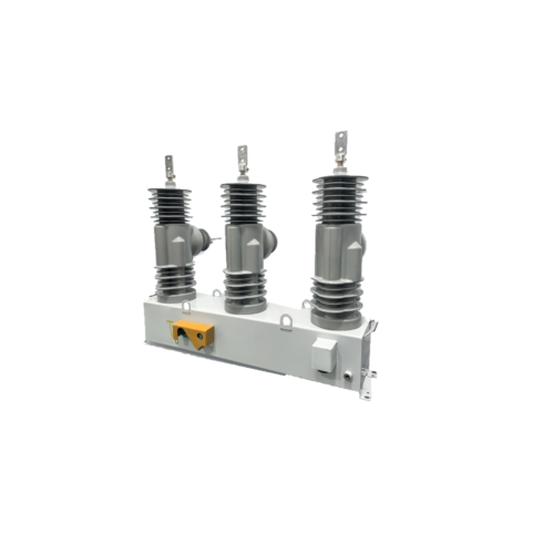
Sectionalize distribution feeders with an MPP-LBS load switch paired with a sectionalizing controller. Select the voltage version and coordinate the control logic with upstream protection, the feeder layout and the required automation interfaces.

Sectionalize distribution feeders with an MPP-LBS load switch paired with a sectionalizing controller. Select the voltage version and coordinate the control logic with upstream protection, the feeder layout and the required automation interfaces.
The MPP-LBS automatic-sectionalizer configuration pairs the load switch with a sectionalizing controller. The selected controller and operating logic define how the package responds within the feeder protection scheme. Specify the voltage version, sensing inputs, auxiliary supply and communications together. Confirm switching and withstand duties for that version and coordinate operation with the upstream protective device.
| Electrical parameter | Specification |
|---|---|
| Product configuration | MPP-LBS load switch with sectionalizing controller |
| Voltage versions | 12 / 24 / 38 kV |
| Rated current | 630 A |
| Operating modes | Manual / electric / automatic, by selected configuration |
| Insulation and interruption medium | SF6 switch arrangement |
| Short-time withstand duty | Obtain the confirmed voltage-specific current and duration |
| Insulation levels | Obtain the confirmed voltage-specific schedule |
| Control coordination | Define operating logic, reset and loss-of-voltage behavior |
Confirm the selected assembly, component ratings and verification documents. Family options do not describe every supplied configuration.
Match the equipment configuration to the circuit duty and installation interfaces.
| Selection item | Specification / requirement |
|---|---|
| Switch body | Select the voltage version and mechanical installation |
| Sectionalizing controller | Agree the control type, logic and pairing with the switch |
| Sensing and signals | Define voltage/current inputs and indication requirements |
| Local control | Specify manual and electrical operating interfaces |
| Automation interface | Confirm the required terminal, protocol and communications equipment |
The sectionalizing controller is essential to the automatic-sectionalizer scope. A plain MPP-LBS switch without the agreed control package is a different configuration.
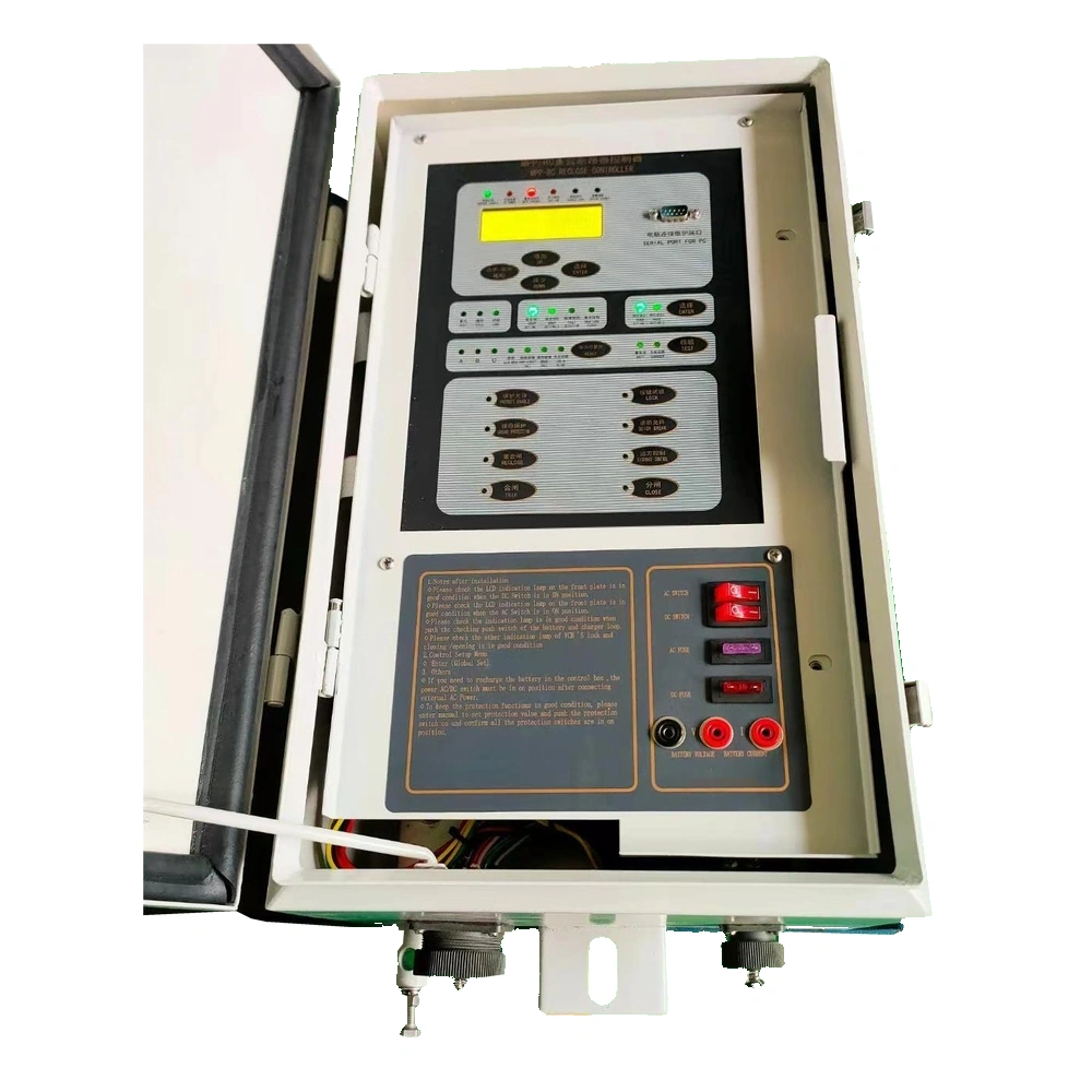
mpp lbs controller.webp
Define the required behavior with upstream protective devices and the feeder operating sequence.
Confirm counting or timing logic where used, reset conditions, voltage-loss response and blocking rules.
A short-time withstand value does not establish short-circuit breaking duty. Verify the required switching duty for the selected package.
The load break switch duty guide separates normal-load interruption, isolation and fault-clearing requirements.
Agree remote commands, indications and protocols only for the selected control equipment.
Functional overview only. Qualified personnel must follow the approved isolation procedures and supplied operating instructions.
Define the equipment duty and interfaces before requesting the project configuration.
| Configuration item | Purpose | Define for your project |
|---|---|---|
| Load-switch body | Perform the selected switching duty | Voltage, current and verified withstand schedule |
| Sectionalizing control | Apply the agreed feeder isolation logic | Upstream coordination, timing and reset |
| Sensing | Provide inputs to the selected control | Sensor type, ratios and signal requirements |
| Communication | Connect automation where required | Protocol, ports and remote functions |
| Installation accessories | Complete the mechanical and electrical interfaces | Brackets, cables, connectors and power supply |
Final components and scope of supply are defined in the project quotation.
| Interface | Reference / requirement | Selection note |
|---|---|---|
| Pole attachment | Confirm the selected bracket and support details | Provide pole geometry and installation height |
| Terminals and clearances | Confirm the voltage-specific terminal arrangement | Provide conductor and clearance requirements |
| Controller location | Confirm mounting and operating access | Define switch-to-controller distance |
| Control cable | Confirm cable length, connectors and routing | Coordinate support and cable entry |
| Service access | Allow operation, inspection and controller maintenance | Approve the complete installation arrangement |
Use the approved project drawing for dimensions, clearances, foundations and connections.
Send voltage, frequency, load current, fault level, feeder diagram and upstream protection details.
Approve the pole bracket, terminations, controller support and interconnection cable.
Define supply source, backup requirements and behavior after power loss.
Request the switch rating schedule, controller logic description, wiring diagrams and project functional checks.
| Condition | Requirement / project input |
|---|---|
| Application | Distribution-feeder sectionalizing and fault-zone isolation |
| Site environment | State temperature, altitude, pollution and wind or ice conditions |
| Gas and enclosure data | Confirm filling, monitoring and service requirements for the selected unit |
| Control supply | Define normal and backup power requirements |
| Network coordination | Provide the upstream protection and restoration strategy |
Provide any conditions outside the stated range before ordering. Final suitability requires project-specific confirmation.
Coordinate the switch-controller package with upstream protection and the intended feeder operating sequence.
Define voltage/current sensing, remote signals, local control and communications for the selected controller.
Planning example: a feeder design includes a controlled sectionalizing point. Its response is agreed with the upstream protection and operating policy.
Provide the upstream device settings, feeder layout and required sectionalizing behavior.
Agree any counting or timing logic, reset conditions, voltage-loss response and blocking rules.
Select the switch version, controller, sensing, power supply and wiring, then agree functional verification.
Production follows the approved drawings, the applicable product standards and the agreed inspection plan.
We can adjust the configuration for your operating environment and provide neutral packaging or your logo. Send the site conditions and branding requirements with your enquiry.
Incoming components, production work and finished units are checked against the requirements for the ordered configuration.
Incoming materials and components are checked against the approved specifications before production.
Assemblies and semi-finished components are inspected at the relevant production stages.
Finished equipment and release records are checked against the approved order requirements.
Factory acceptance testing (FAT). Every unit undergoes FAT before packing. Test items and acceptance criteria follow the product and approved configuration. FAT reports and packing inspection photos accompany the shipment. Factory attendance, video witnessing or independent inspection can be arranged with an agreed scope and schedule.
Send your required ratings, installation conditions and quantity. We will confirm the configuration and documents for your quotation.
Selected voltage version and coordinated control package.
Sensing, auxiliary power, signals and sectionalizing sequence.
Electrical duty and verification of the agreed control sequence.
The automatic-sectionalizer configuration adds a sectionalizing controller and an agreed operating logic. Confirm the switch-controller package and its interfaces.
The duties and control strategy must be specified separately. Coordinate this sectionalizer with upstream protection and confirm any required fault-interruption duty.
No. Select one version and obtain its complete current, insulation and withstand schedule.
These control approaches are described in the supporting product material. The exact controller pairing, logic and interfaces require project confirmation.
Send the feeder diagram, voltage and frequency, load and fault levels, upstream settings, sectionalizing strategy, control supply and communication requirements.