Request a Quote
Share your product list, technical ratings, quantity and delivery destination.
Load-breaking, isolation and fault-clearing duties require different checks. Compare transformer switch arrangements and define the RFQ fields for the correct assembly.
A load break switch makes and interrupts specified load currents. Its load-breaking duty is different from isolating a circuit or clearing a short circuit. For selection, identify the duty first, then match the switch ratings, protection arrangement and mechanical interfaces. A transformer’s internal two- or four-position switch and a three-pole switch in medium-voltage switchgear serve different assemblies; the same search term can lead to either product.
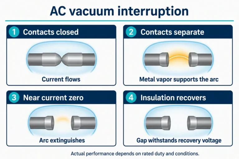
Opening contacts creates an arc. A load-break device uses its interruption system to extinguish that arc within its rated switching duties. The useful procurement question is therefore not simply whether the switch opens, but what current it can interrupt, at what voltage and under which circuit conditions.
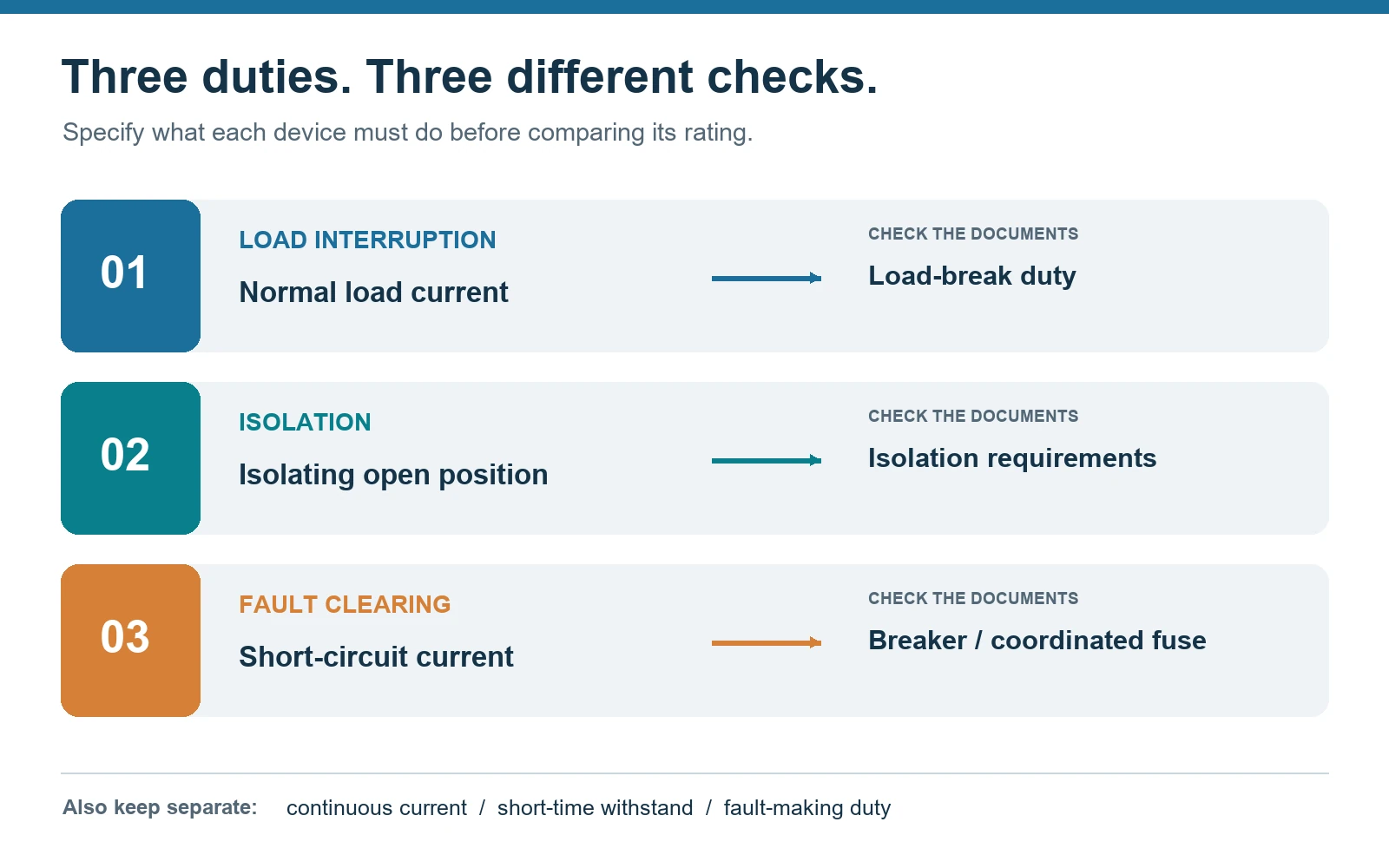
IEC 62271-103:2021 distinguishes switches by their making and breaking capabilities. Its scope covers AC switches and switch-disconnectors above 1 kV through 52 kV. It also treats the disconnecting function separately. These distinctions help separate three requirements often compressed into the phrase “disconnect switch.”
| Required function | What the device must do | Evidence to request |
|---|---|---|
| Load interruption | Make and break the specified normal-load circuit. | Rated breaking current, circuit duty, rated voltage and operating conditions. |
| Isolation | Provide the required isolating function in the open position. | Switch-disconnector designation, applicable requirements and the assembly’s isolation arrangement. |
| Fault interruption | Clear the prospective short-circuit current. | Fault-breaking ratings and the selected circuit breaker or fuse-protection arrangement. |
Keep continuous current, load-breaking current, short-time withstand current and fault-making current in separate datasheet fields. A high withstand or fault-closing value does not describe the current the switch can interrupt. For example, S&C’s Mini-Rupter rating table lists continuous, interrupting, peak-withstand and fault-closing values in distinct columns. Comparing quotations becomes more reliable when suppliers use the same headings.
A switch-disconnector combines a switching function with the isolating requirements applicable to its open position. An “open” indication alone does not establish that function. IEC 62271-103 directs the disconnecting function to IEC 62271-102; check the offered equipment’s declaration and documents rather than inferring isolation from its name.
Fault clearing requires another check. The switch definition in IEC 62271-103 allows carrying short-circuit current for a specified time and, for some switches, making short-circuit current. It does not give the switch short-circuit breaking capability. A switch-fuse combination assigns protection duties to a coordinated combination, while a breaker-based arrangement uses a circuit breaker and its protection system.
This distinction affects the equipment schedule. Specify which device clears a fault, which device interrupts load during normal switching, and which arrangement provides isolation. If a quotation changes from a switch-fuse feeder to a breaker feeder, review the protection and operating arrangement as well as the price. The medium-voltage switchgear guide puts these devices in the context of the complete assembly.
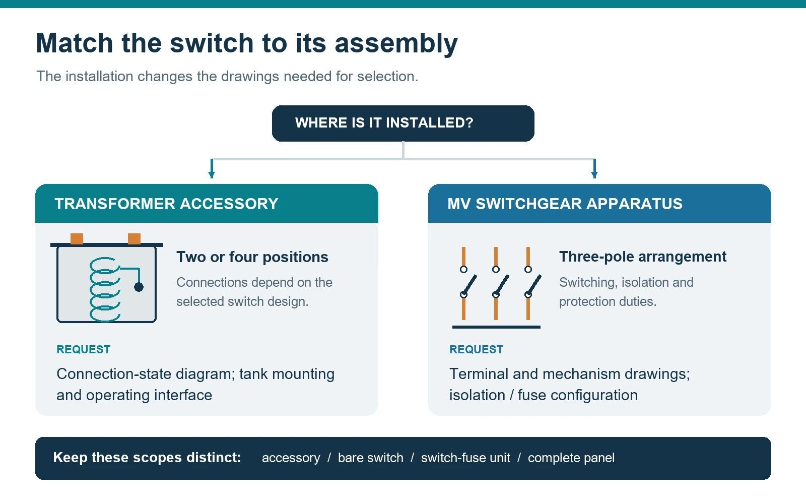
A transformer load break switch can be an accessory installed inside the transformer tank, with its operating interface outside. This is a different selection task from buying a freestanding switchgear mechanism. The transformer’s primary connection layout, internal leads, mounting interface and required switching states govern the accessory choice.
Two-position arrangements provide on/off control. Four-position arrangements are used for additional connection choices, commonly in loop-feed transformers. Maddox’s transformer switch guide explains the difference between two-position arrangements and four-position switches with different blade configurations. Its examples show why the position count cannot replace a connection diagram.
For a four-position request, label the two feeder sides and the transformer winding on the supplier’s state diagram. Ask the supplier to show which terminals remain connected in each position. In some configurations, a feeder path can remain connected while the transformer winding is disconnected. An “open” description without identifying the circuit leaves that distinction unresolved.
Send the transformer drawing, switch mounting details, operating-shaft arrangement and terminal identification with the enquiry. Use the transformer specification checklist to keep the accessory requirement tied to the whole transformer order. If the specification says “LBOR,” retain the supplier’s exact term and obtain its model and connection drawing; the abbreviation alone is not an ordering description.
“Air-break” describes an interruption or contact arrangement; “gang-operated” describes linked operation of multiple poles. Neither phrase, by itself, supplies a breaking-current rating. A three-phase interrupting switch must be identified by its actual construction and documented switching duties, not just by the presence of three poles or a common handle.
Some disconnect arrangements obtain load interruption from an additional device. S&C’s Loadbuster documentation, for example, describes a portable loadbreak tool used with compatible disconnects, cutouts and other equipment. That capability belongs to the specified arrangement; it should not be transferred to an arbitrary air-break disconnect.
A “15 kV switch” enquiry is also incomplete. State the system voltage, required equipment rating, insulation level, frequency and current duties. Then identify whether the scope is a bare switch, a switch-fuse combination or a complete panel. A transformer accessory, separable connector and medium-voltage switchgear assembly should not occupy the same line item merely because each catalogue uses “load break.”
Start with a single-line diagram and a function statement: what circuit is switched, what must remain connected, and what device clears a fault. The following fields turn that statement into comparable supplier responses.
| RFQ field | Specify or attach | Check in the quotation |
|---|---|---|
| System and environment | Voltage, frequency, earthing arrangement, indoor/outdoor location, altitude and ambient conditions. | Ratings and any conditions affecting the offered configuration. |
| Switching duty | Load type, continuous current, required breaking duties and operating frequency. | Separate carrying and breaking ratings; any circuit-specific limits. |
| Fault duty and protection | Prospective fault current, clearing time and intended protection arrangement. | Withstand/making duties, fault-clearing device and coordination documents. |
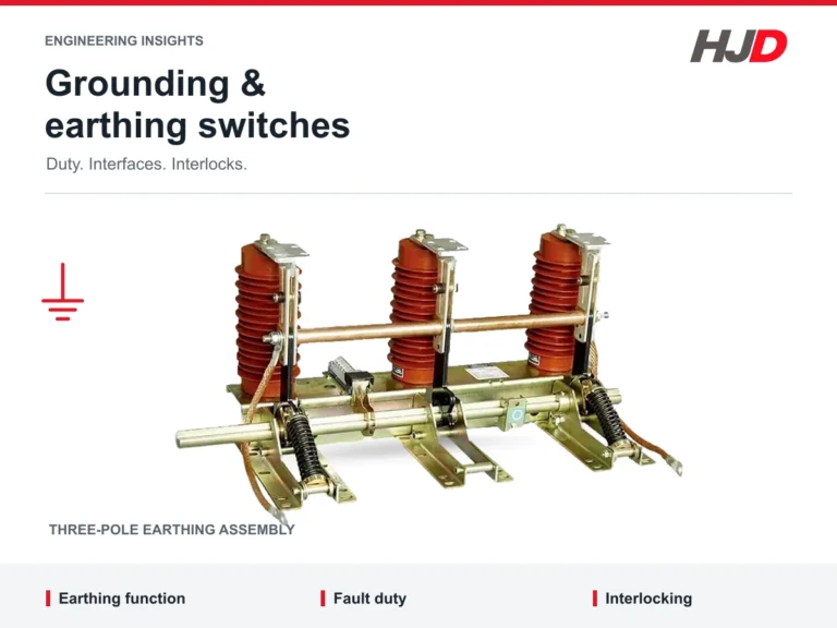
| Isolation and earthing | Required isolation function, earthing provision and interlocking sequence. | Exact switch-disconnector and earthing-switch configuration. |
| Connection states | Single-line diagram; transformer two-/four-position state diagram where relevant. | Terminal identification and connections in every position. |
| Mechanical and control interfaces | Mounting drawing, terminal layout, operating access, manual/motor operation and auxiliary signals. | Dimensions, mechanism interfaces, indication and wiring drawings. |
| Delivered scope | Bare apparatus, transformer accessory, switch-fuse unit or complete switchgear assembly. | Model-specific datasheet, drawings, applicable test documentation and included accessories. |
For transformer feeders, identify whether the request includes fuse protection. HJD’s FKN12 / FKRN12 product page separates the load-switch family from the fuse-combination family. Use the selected variant and fuse arrangement in the equipment schedule, rather than treating the two names as interchangeable.
Before accepting the offer, trace the model designation through the datasheet, dimensional drawing, state diagram and quotation. A change to the mechanism, fuse, terminal orientation or auxiliary contacts should appear in the same document set. This catches interface differences before panel fabrication or transformer assembly begins.
Not when the circuit needs the device to interrupt a short circuit. Compare load interruption, fault interruption and protection requirements separately. A switch-fuse combination may meet a particular feeder requirement, but its fuse selection and combination duties must match that application.
No. Check whether the offered device is a switch-disconnector and whether its open position meets the required isolating function. The equipment’s earthing, interlocking and access arrangements need their own review.
It offers different connection choices, not an automatic performance upgrade. Choose the arrangement from the feeder topology and the required connections in each position. Obtain the state diagram before comparing prices.
Suppliers use LBOR in transformer load-break-switch descriptions. For procurement, ask for the manufacturer, exact model, ratings and position diagram. Those fields identify the required accessory more reliably than the abbreviation.
Send the single-line diagram, voltage and current duties, fault level, required isolation function and installation drawing with your load break switch enquiry. For transformer accessories, add the connection-state diagram and mounting interface. That gives the supplier a defined switching task and a clear equipment scope to quote.