Request a Quote
Share your product list, technical ratings, quantity and delivery destination.
APPLICATIONS / INDUSTRIAL
HJD supplies MV switchgear, transformers and LV cabinets for new factories, workshop extensions and equipment replacement.
New factory / Added capacity / Equipment upgrade
01 / SUPPLY ARRANGEMENT
Available supply, load behavior and existing interfaces determine which equipment changes.
1
The supply connection sets the incoming voltage and fault duty. Motors, drives and workshop services define the downstream load requirements.
HJD uses the project load list to define the incoming switchgear, transformer and LV feeder schedule.
2
A spare feeder does not establish spare transformer or cable capacity. Starting a large motor may also constrain a system that can carry its running load.
Compare an extension of the existing supply with a new transformer and distribution block. The chosen arrangement needs a fault-duty and protection-coordination review.
3
The new equipment must match the existing voltage, current ratings, busbars, cable terminations, control power and interlocks.
HJD uses existing drawings, dimensions and nameplates to specify the replacement package and its connection points.
02 / COMPARE OPTIONS
OPTION A
Use the existing intake and transformer, with the additional switching and feeders the project needs.
OPTION B
Provide another transformer and its associated MV switching and LV distribution.
03 / EQUIPMENT & INTERFACES
Product families below are starting points. The project ratings and interface schedule determine the configuration.
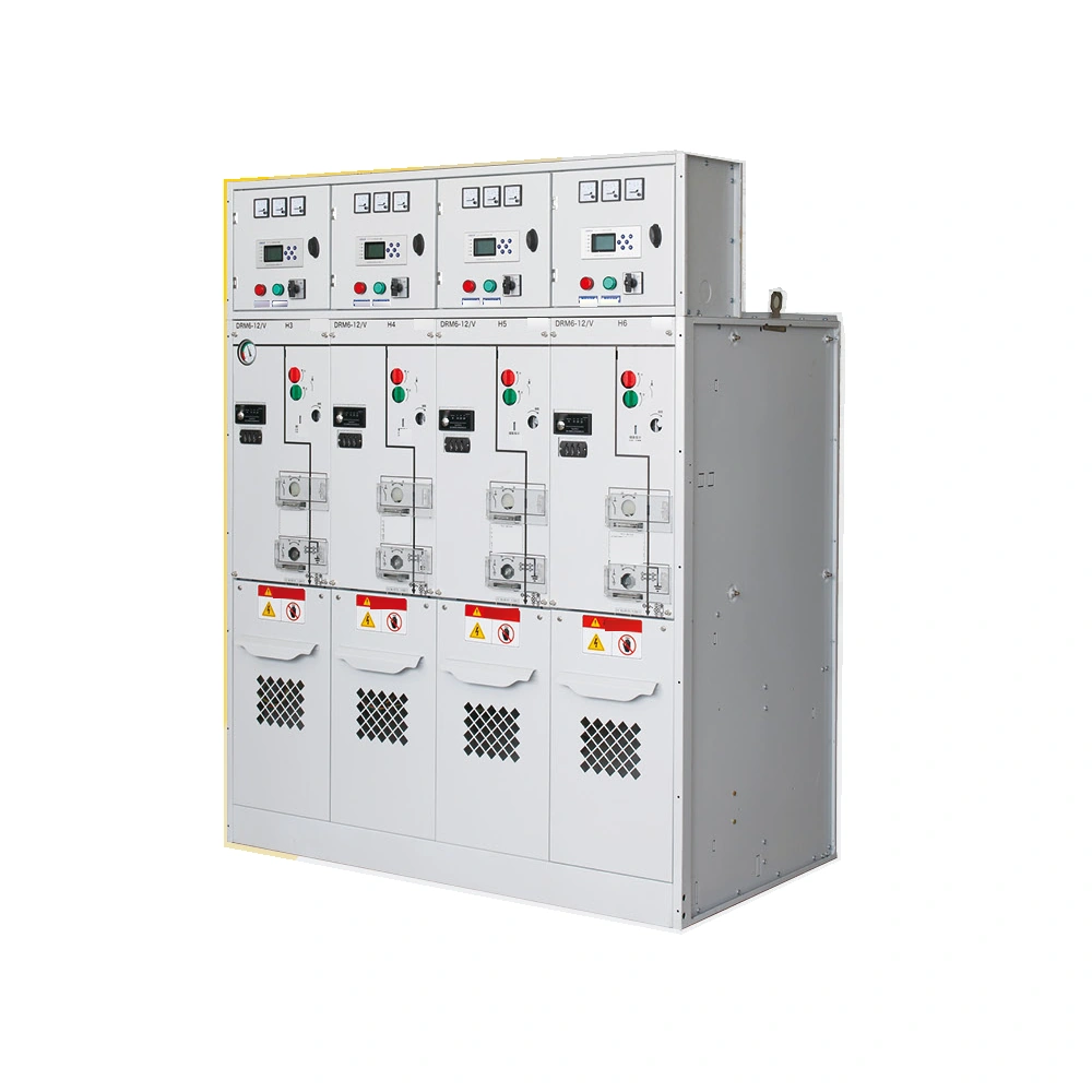
INCOMING & FEEDER SWITCHING
DRM6-12 ring main unit
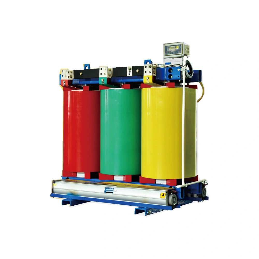
VOLTAGE & LOAD MATCHING
SC(B)13 dry-type series
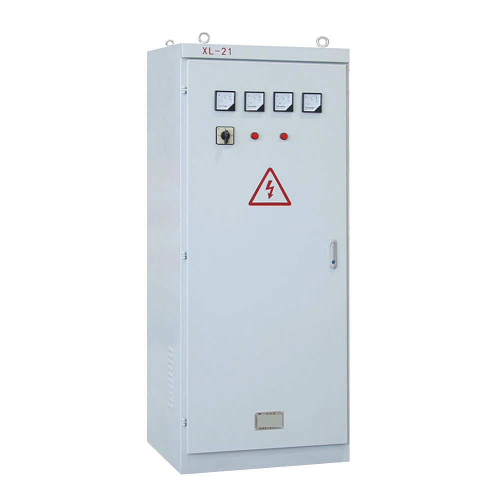
OUTGOING WORKSHOP CIRCUITS
XL-21 distribution series
04 / FAQ
Review measured kW, kVA, power factor and the load profile. Capacitor banks can reduce the reactive demand of inductive loads. Drives and other nonlinear loads also require a harmonic review before compensation is selected. Existing filters, switching steps and the connection point affect the arrangement.
Start with the incoming and required secondary voltage, simultaneous operating load and planned expansion. Include motor-starting duty and nonlinear loads, then check the installation environment, cooling and connection arrangement. Send the load list and supply diagram so the transformer and its upstream and downstream equipment can be specified together.
Check measured peak demand and the capacity of the intake, transformer, busbars and cables. Add the new load and its starting requirements, then review fault duty and protection coordination. If capacity or interfaces constrain an extension, compare a separate transformer and distribution block.
An extension depends on the condition and ratings of the existing lineup, available space and a compatible busbar connection. Replacement may be needed where ratings, condition or interfaces prevent an extension. Keep the original drawings, protection information and dimensions available for the review.
Use the equipment manufacturer’s maintenance instructions and a site-specific schedule. Dust, moisture, corrosive conditions, operation count and equipment condition can change the interval. A qualified maintenance team should plan isolation, inspections and tests for the installed equipment.
Overload protection addresses sustained loading and temperature rise; short-circuit protection addresses faults. The protection design must account for the transformer’s thermal limits, inrush and coordination with connected equipment. Include temperature sensors, alarms and trip interfaces in the equipment specification where the design requires them.
Send your product list, technical ratings, quantity and delivery destination.
