Request a Quote
Share your product list, technical ratings, quantity and delivery destination.

A floor-standing low-voltage cabinet for power distribution, lighting and motor circuits. Configure the incomer, outgoing protection and metering around the circuit schedule, then coordinate the enclosure dimensions and cable access with the installation.
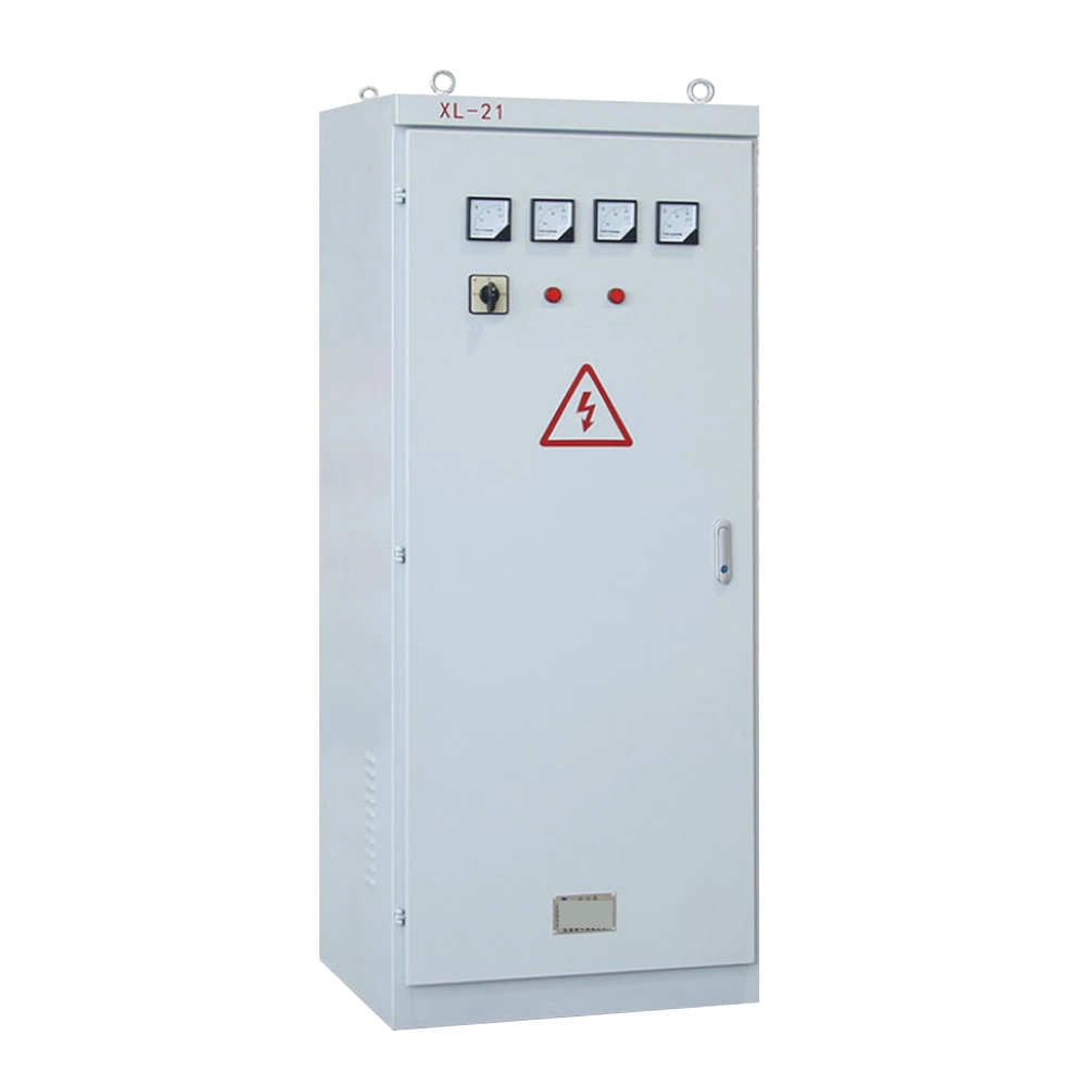
A floor-standing low-voltage cabinet for power distribution, lighting and motor circuits. Configure the incomer, outgoing protection and metering around the circuit schedule, then coordinate the enclosure dimensions and cable access with the installation.
XL-21 houses the incoming device, outgoing protective devices and selected control or metering equipment in a floor-standing cabinet. It serves power, lighting and specified motor circuits. The load and circuit schedule set the device layout. Cabinet size and cable access are selected after checking the incoming arrangement and the space needed for connections.
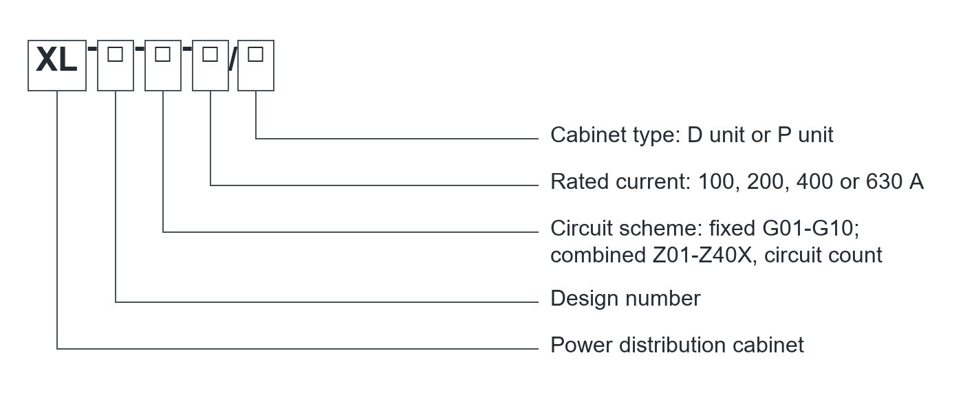
| Electrical parameter | Specification |
|---|---|
| Product family | XL-21 power distribution cabinet |
| System arrangement | Three-phase, four-wire |
| Frequency | 50 Hz |
| Reference operating voltage | 380 V AC |
| Series voltage scope | Below 660 V; confirm the selected design |
| Listed current codes | 100 / 200 / 400 / 630 A |
| Reference enclosure protection | IP30; confirm the complete selected assembly |
| Operation | Manual operating arrangement |
| Connection method | Fixed wiring |
Confirm the selected assembly, component ratings and verification documents. Family options do not describe every supplied configuration.
Select the electrical arrangement and interfaces for the intended duty.
| Selection item | Specification / requirement |
|---|---|
| Incomer | Disconnecting switch or circuit breaker, as selected |
| Outgoing circuits | Fuse or circuit-breaker protection to suit the load |
| Motor circuits | Contactor and thermal protection where specified |
| Metering | Voltmeter, ammeter and selected current transformers |
| Circuit arrangement | Fixed or combined circuit scheme |
| Auxiliary circuit | Approved control schematic and component list |
The selected order code and approved drawings define the delivered equipment.
Specify the incoming device and handle arrangement. Confirm isolation and lockout requirements against the approved circuit.
Select each protective device for the connected load and fault conditions. Component breaking ratings do not automatically establish an assembly rating.
Provide motor ratings, starting method and control requirements when contactors or thermal relays are needed.
Functional overview only. Qualified personnel must follow the approved isolation procedures and supplied operating instructions.
Define the equipment duty and interfaces before requesting the project configuration.
| Configuration item | Purpose | Define for your project |
|---|---|---|
| Distribution | Allocate circuits | Load schedule, incomer and outgoing feeders |
| Motor control | Coordinate starting and protection | Motor ratings and operating method |
| Metering | Provide required readings | Metering functions and CT ratios |
| Installation | Fit the available space | Dimensions, cable entries, access and anchoring |
Final components and scope of supply are defined in the project quotation.
| Interface | Reference / requirement | Selection note |
|---|---|---|
| Compact reference | 500 x 700 x 200 mm | Width x height x depth |
| Intermediate reference | 600 x 1200 x 350 mm | Select the circuit layout first |
| Tall reference | 800 x 2000 x 450 mm | Confirm access and cable-bending space |
| Cable access | Project arrangement drawing | Cable count, conductor sizes and entry direction |
Reference dimensions support layout planning. Use the approved drawing for installation.

XL-21 outline
Provide a level mounting location, anchor arrangement and front service space.
Submit incoming and outgoing cable sizes, entry direction and termination requirements before the cabinet layout is approved.
Check the installed assembly and wiring against the approved drawings and supplied instructions before energization.
| Condition | Requirement / project input |
|---|---|
| Location | Confirm the intended indoor or protected installation |
| Altitude | Up to 2000 m in the reference conditions |
| Upper ambient | +40 C maximum; +35 C average over 24 hours |
| Low ambient | Confirm the project minimum temperature |
| Atmosphere | Avoid corrosive or explosive gases and excessive contamination |
| Condensation | Declare humidity and condensation exposure for design review |
Provide any conditions outside the stated range before ordering. Final suitability requires project-specific confirmation.
Arrange incoming and outgoing protection for the workshop power and lighting circuits.
Include the specified contactors, thermal protection and control wiring for the connected motors.
Coordinate cabinet footprint, front access and cable routes with the installation area.
A planning example for turning a workshop circuit list into an XL-21 equipment and enclosure arrangement.
Provide supply voltage, loads, outgoing circuits and fault conditions.
Define the incomer, feeder protection, motor controls and metering required.
Check cable space, front service access, cabinet dimensions and installation environment.
Production follows the approved drawings, the applicable product standards and the agreed inspection plan.
We can adjust the configuration for your operating environment and provide neutral packaging or your logo. Send the site conditions and branding requirements with your enquiry.
Incoming components, production work and finished units are checked against the requirements for the ordered configuration.
Incoming materials and components are checked against the approved specifications before production.
Assemblies and semi-finished components are inspected at the relevant production stages.
Finished equipment and release records are checked against the approved order requirements.
Factory acceptance testing (FAT). Every unit undergoes FAT before packing. Test items and acceptance criteria follow the product and approved configuration. FAT reports and packing inspection photos accompany the shipment. Factory attendance, video witnessing or independent inspection can be arranged with an agreed scope and schedule.
Send your required ratings, installation conditions and quantity. We will confirm the configuration and documents for your quotation.
Incoming, outgoing, motor-control and metering selections.
Cabinet dimensions, device arrangement and cable entry.
Applicable assembly evidence and factory inspection records.
XL-21 provides low-voltage distribution for power, lighting and selected motor circuits. The circuit schedule determines the installed devices.
No. The family includes 100, 200, 400 and 630 A order codes. Confirm the rating of the selected incoming circuit and assembly.
Confirm the actual enclosure and environment first. The listed IP30 reference does not establish suitability for rain or exposed outdoor service.
No. Several enclosure sizes are listed. Device layout, cable space and access requirements determine the selected size.
Send the single-line diagram, load and circuit schedule, supply voltage, fault conditions, component preferences and installation dimensions.