Request a Quote
Share your product list, technical ratings, quantity and delivery destination.
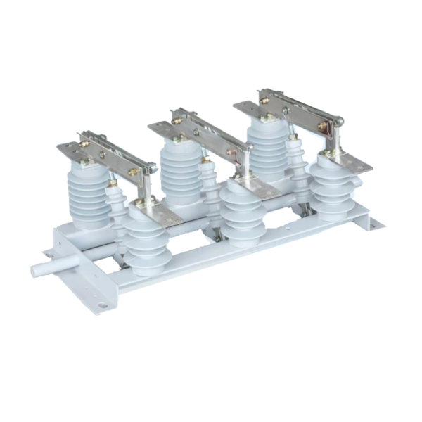
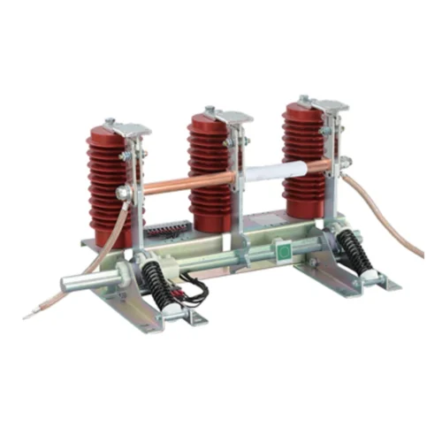
Provide indoor isolation for a 12 kV circuit using a manually operated disconnect switch. GN19-12 is intended for switching without load current; select the current rating, mounting arrangement and CS6-1 operating mechanism interface for the panel.
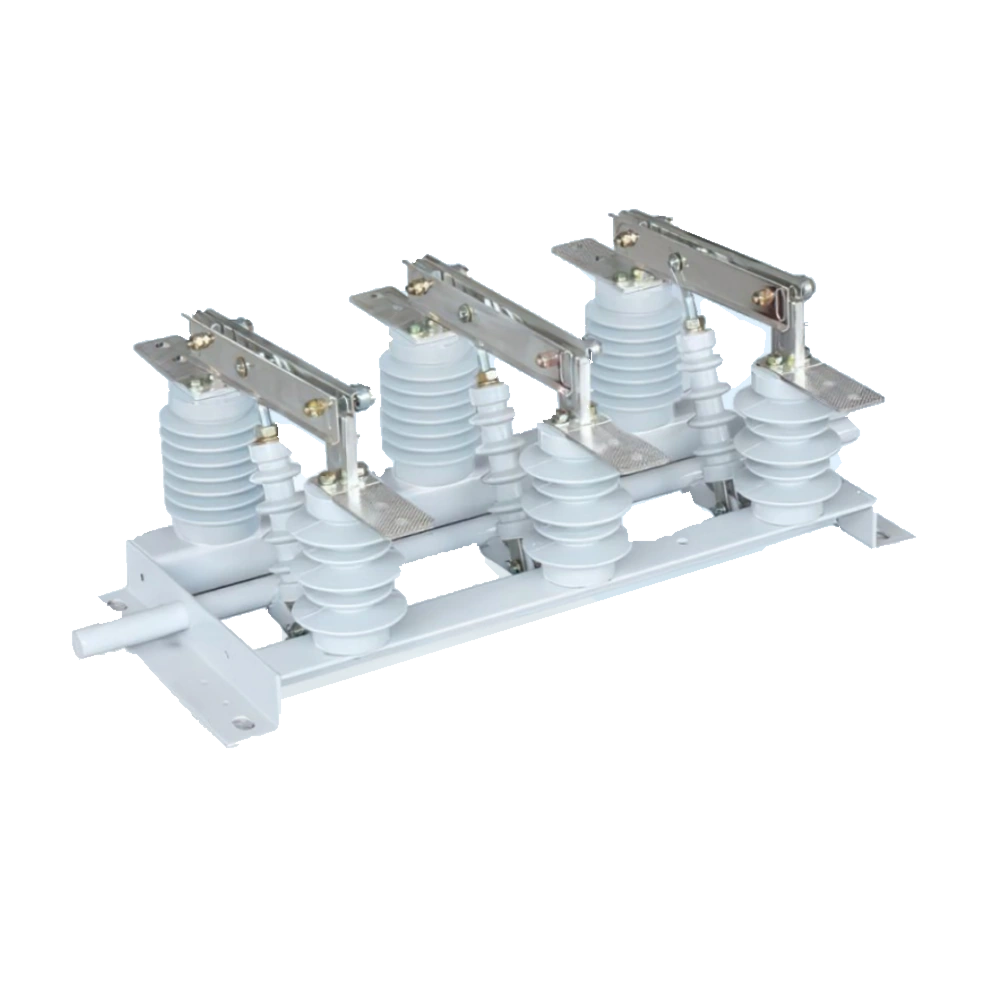
Provide indoor isolation for a 12 kV circuit using a manually operated disconnect switch. GN19-12 is intended for switching without load current; select the current rating, mounting arrangement and CS6-1 operating mechanism interface for the panel.
GN19-12 provides manual no-load isolation in an indoor circuit. Select the continuous current and mounting variant with the primary terminals and cabinet layout. The CS6-1 mechanism, shaft and linkage must suit the operating position. The panel interlocks and operating procedure must establish the required no-load condition before the switch is operated.
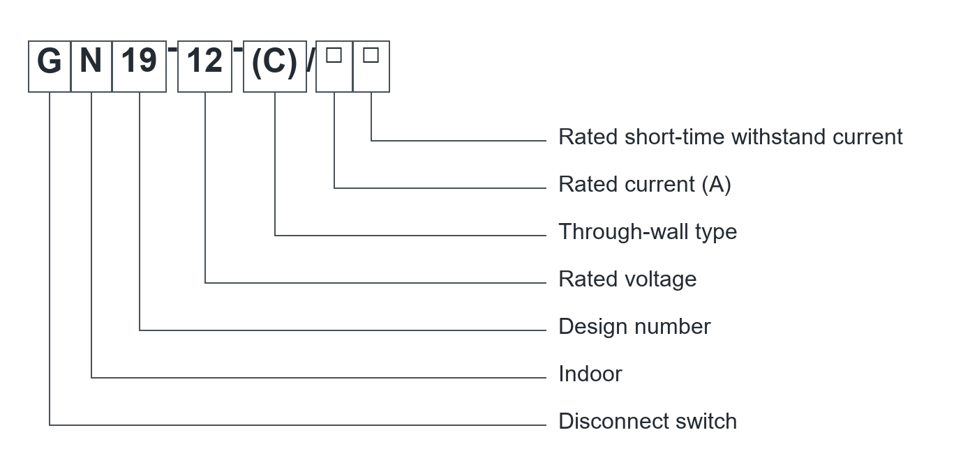
C identifies the through-wall variant. The two adjacent blank fields follow the original catalogue notation.
| Electrical parameter | Specification |
|---|---|
| Model family | GN19-12 |
| Rated voltage | 12 kV |
| Rated frequency | 50 Hz |
| Rated-current options | 400 / 630 / 1000 / 1250 A |
| One-minute withstand to earth | 42 kV |
| One-minute withstand across open gap | 48 kV |
| Impulse withstand to earth | 75 kV |
| Impulse withstand across open gap | 85 kV |
| Short-time and peak withstand | Select the matched schedule for the ordered current variant |
| Switching duty | No-load isolation; not a load break or fault-interrupting device |
Confirm the selected assembly, component ratings and verification documents. Family options do not describe every supplied configuration.
Match the equipment configuration to the circuit duty and installation interfaces.
| Selection item | Specification / requirement |
|---|---|
| Current rating | Select 400, 630, 1000 or 1250 A against the circuit duty |
| Mounting variant | Confirm the standard or through-wall configuration |
| Manual mechanism | Match the CS6-1 operating mechanism and linkage |
| Terminal arrangement | Confirm primary connection dimensions and conductor direction |
| Interlocking | Define isolation, breaker and access interlocks with the panel |
Confirm the selected order code and component schedule before approval.
Establish the required no-load condition before operating, using the approved electrical isolation procedure.
Match handle, shaft and linkage travel to the selected device and cabinet.
Coordinate with the upstream switching device and access sequence to prevent an unsuitable operation.
Confirm the visible position, auxiliary contacts where required and panel labelling.
Functional overview only. Qualified personnel must follow the approved isolation procedures and supplied operating instructions.
Define the equipment duty and interfaces before requesting the project configuration.
| Configuration item | Purpose | Define for your project |
|---|---|---|
| Main disconnect | Provide the selected isolation function | Voltage, current and withstand duty |
| Manual mechanism | Operate the selected device | CS6-1 interface, shaft and handle location |
| Mounting variant | Fit the panel or through-wall arrangement | Support, phase spacing and insulation geometry |
| Interlocks | Coordinate the isolation and access sequence | Breaker status, access rules and operating scheme |
| Connection package | Match the primary conductors | Busbar dimensions, terminals and approved drawing |
Final components and scope of supply are defined in the project quotation.
| Interface | Reference / requirement | Selection note |
|---|---|---|
| Standard arrangement | Request the selected GN19-12 outline | Confirm support spacing, phases and terminal positions |
| Through-wall arrangement | Request the exact through-wall variant drawing | Match wall opening, insulation and support |
| Operating shaft | Confirm shaft position, handle direction and linkage travel | Provide the panel arrangement |
| Terminals | Confirm the drawing for the selected current rating | Match busbar dimensions and hole pattern |
| Open position | Check blade travel and insulation space | Approve the complete compartment layout |
Use the approved project drawing for dimensions, clearances, foundations and connections.
Approve mounting holes, phase spacing, terminals, open-blade space and operating linkage.
Provide system voltage, frequency, continuous current and short-circuit withstand requirements.
Specify standard or through-wall mounting and the exact current code.
Request the selected outline, operating instructions, rating schedule and applicable verification records.
| Condition | Requirement / project input |
|---|---|
| Location | Indoor |
| Network | 12 kV, 50 Hz selection basis |
| Environment | State temperature, altitude, humidity and contamination |
| Switching condition | Operate only within the confirmed no-load duty |
| Installation | Panel clearances and mechanism travel must match the approved drawing |
Provide any conditions outside the stated range before ordering. Final suitability requires project-specific confirmation.
Coordinate the disconnect switch with the main switching device, earthing scheme and panel access sequence.
Check standard or through-wall mounting, terminal positions and the existing manual mechanism before selecting a unit.
Planning example: a panel design needs a GN19-12 disconnect with an accessible manual operating position and a defined isolation sequence.
Provide circuit current, fault-withstand requirements and the standard or through-wall mounting choice.
Locate the CS6-1 handle, shaft and linkage, and check travel against the selected switch drawing.
Coordinate the main device, no-load operating condition, access sequence and any auxiliary contacts.
Production follows the approved drawings, the applicable product standards and the agreed inspection plan.
We can adjust the configuration for your operating environment and provide neutral packaging or your logo. Send the site conditions and branding requirements with your enquiry.
Incoming components, production work and finished units are checked against the requirements for the ordered configuration.
Incoming materials and components are checked against the approved specifications before production.
Assemblies and semi-finished components are inspected at the relevant production stages.
Finished equipment and release records are checked against the approved order requirements.
Factory acceptance testing (FAT). Every unit undergoes FAT before packing. Test items and acceptance criteria follow the product and approved configuration. FAT reports and packing inspection photos accompany the shipment. Factory attendance, video witnessing or independent inspection can be arranged with an agreed scope and schedule.
Explore related guides for product selection, specifications and project planning.
Check power paths, protection, controls and equipment interfaces.
It is specified here for no-load isolation. Use a correctly rated load switch or circuit breaker for duties that require load or fault interruption.
This page covers the manual configuration and CS6-1 mechanism interface. A motor-operated requirement needs a separately confirmed product configuration.
Match the continuous current and the complete short-time/peak withstand schedule to the circuit and installation conditions.
A through-wall arrangement is shown in the product material. Confirm the exact variant, current rating and installation drawing before order.
Send voltage, frequency, current, fault-withstand requirements, mounting variant, panel drawing, manual mechanism location and required interlocks.