Request a Quote
Share your product list, technical ratings, quantity and delivery destination.
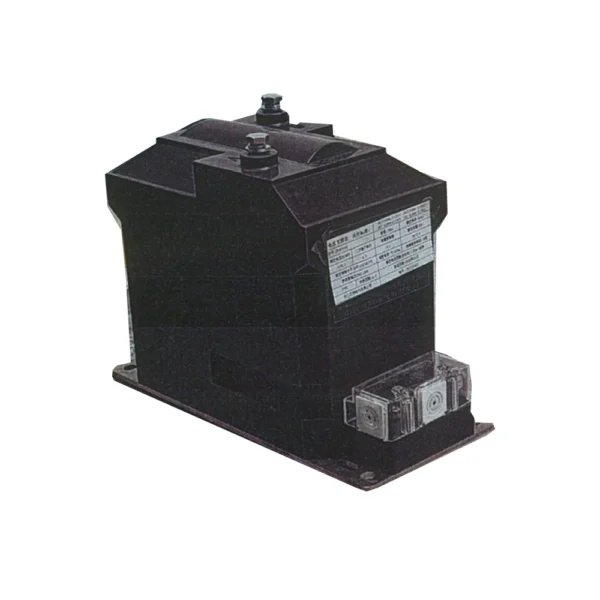
An indoor epoxy-resin cast voltage transformer for metering circuits. The inspected JDZ10-10 sample has a 10/0.1 kV ratio and accuracy class 0.2. Confirm the voltage ratio, winding arrangement, burden and mounting details for the intended circuit.
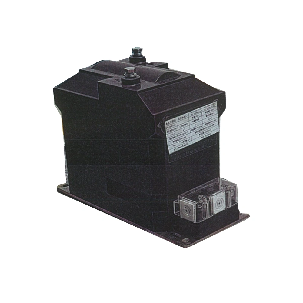
An indoor epoxy-resin cast voltage transformer for metering circuits. The inspected JDZ10-10 sample has a 10/0.1 kV ratio and accuracy class 0.2. Confirm the voltage ratio, winding arrangement, burden and mounting details for the intended circuit.
JDZ10-10 is an indoor epoxy-resin cast voltage transformer for metering. The reference sample has a 10/0.1 kV ratio and accuracy class 0.2. Confirm the winding arrangement and connection scheme with the voltage ratio, burden and accuracy requirement. The ordered drawing defines mounting and terminal interfaces.
| Electrical parameter | Reference sample / requirement |
|---|---|
| Model | JDZ10-10 |
| Transformer type | Indoor voltage transformer |
| Reference ratio | 10/0.1 kV |
| Reference accuracy class | 0.2 |
| Reference frequency | 50 Hz |
| Reference insulation level | 12/42/75 kV |
| Insulation construction | Epoxy-resin cast reference sample |
| Rated burden | Confirm VA, power factor and the accuracy conditions for the ordered configuration |
Reference sample data. Confirm the ordered ratio, accuracy class, burden and applicable verification records before selection.
Define the primary and secondary voltages, connection arrangement and winding duties. Match the accuracy and burden schedule to the metering circuit.
| Selection item | Reference / requirement | Confirm for your project |
|---|---|---|
| Voltage ratio | 10/0.1 kV reference sample | Required primary and secondary voltages |
| Metering accuracy | Class 0.2 reference sample | Required class, rated burden and applicable accuracy conditions |
| Winding arrangement | Confirm the offered configuration | Number of secondary windings, duty and terminal arrangement |
| Connection scheme | Use the approved project diagram | Network connection, meter inputs and earthing design |
| Secondary burden | Confirm the order-specific schedule | Connected meters, devices, lead details and power factor |
The quotation and approved technical schedule define the supplied configuration. Alternative ratios or duties require confirmation.
Match the primary and secondary voltage ratio to the metering circuit and the intended meter inputs.
Confirm the number of windings, their duties and the connection diagram for the actual project configuration.
Specify accuracy class, rated burden, power factor and the connected devices together. The class 0.2 reference does not define every loading condition.
If protection or another secondary duty is required, request the corresponding verified winding and performance schedule rather than assuming coverage from the metering sample.
Use the model-specific installation instructions and approved wiring diagram. Installation and commissioning require qualified personnel.
Define the voltage-transformer duty and interfaces before requesting the project configuration.
| Configuration item | Purpose | Define for your project |
|---|---|---|
| Voltage ratio | Match the system voltage to the meter input | Primary/secondary voltages, frequency and quantity |
| Winding arrangement | Define the intended secondary circuits | Number of windings, duty, voltage and terminal identification |
| Metering performance | Define the measurement requirement | Accuracy class, rated burden, power factor and connected devices |
| Connection and mounting | Integrate the VT with the panel | Circuit diagram, mounting drawing, terminals and clearances |
| Verification scope | Match the offered unit to its documents | Exact model, ratio, windings, class, burden and applicable records |
Final components and scope of supply are defined in the project quotation.
| Interface | Required information | Why it matters |
|---|---|---|
| Overall outline | Current JDZ10-10 drawing for the offered configuration | Check the available panel space and clearance envelope |
| Mounting base | Hole positions, centres and fixing requirements | Coordinate the panel or support before fabrication |
| Primary terminals | Terminal locations, dimensions and connection details | Match the primary circuit and required clearances |
| Secondary terminals | Winding identification and terminal markings | Match each secondary circuit to the approved wiring diagram |
| Wiring and inspection access | Panel layout and terminal-access envelope | Allow connection, identification and inspection after installation |
Request the drawing for the selected order configuration. Approve all mounting dimensions, terminals and clearances before installation.
Provide the system voltage, frequency, required voltage ratio, metering scheme and intended connection arrangement.
Identify every secondary winding, its voltage, class, burden and connected devices. Confirm the terminal and earthing diagram.
Approve the outline, mounting base, primary-terminal positions, secondary access and insulation clearances before panel fabrication.
Match the delivered nameplate and terminal markings to the approved ratio, winding schedule, installation instructions and available verification records.
| Condition | Requirement / project input |
|---|---|
| Location | Indoor |
| Reference frequency | 50 Hz |
| Reference altitude | Up to 1000 m on the inspected sample nameplate |
| Temperature and humidity | Provide site limits and any condensation risk |
| Installation environment | Confirm enclosure, ventilation, pollution and required insulation clearances |
Provide the actual temperature, humidity, altitude and installation environment for project-specific confirmation.
Match the primary and secondary voltages to the metering circuit and intended meter inputs.
Coordinate the VT mounting, terminals, insulation clearances and connection diagram with the panel.
Verify ratio, winding duties, burden and mechanical interfaces before selecting the replacement.
For a proposed JDZ10-10 installation, define the winding duties and panel interfaces in one enquiry.
Provide primary and secondary voltages, frequency, required windings and the connection diagram.
State accuracy class, burden, power factor and the devices connected to each winding.
Check terminal identification, mounting dimensions, earthing design and required clearances.
Production follows the approved drawings, the applicable product standards and the agreed inspection plan.
We can adjust the configuration for your operating environment and provide neutral packaging or your logo. Send the site conditions and branding requirements with your enquiry.
Incoming components, production work and finished units are checked against the requirements for the ordered configuration.
Incoming materials and components are checked against the approved specifications before production.
Assemblies and semi-finished components are inspected at the relevant production stages.
Finished equipment and release records are checked against the approved order requirements.
Factory acceptance testing (FAT). Every unit undergoes FAT before packing. Test items and acceptance criteria follow the product and approved configuration. FAT reports and packing inspection photos accompany the shipment. Factory attendance, video witnessing or independent inspection can be arranged with an agreed scope and schedule.
Explore related guides for product selection, specifications and project planning.
Check power paths, protection, controls and equipment interfaces.
10/0.1 kV is the inspected reference sample ratio. Send the required primary and secondary voltages so the available configuration can be confirmed.
The reference class must be matched to the actual winding, burden, power factor and accuracy conditions. Request the complete schedule for the offered unit.
No. Confirm the number of windings, terminal arrangement and each winding duty in the quotation and approved technical schedule.
Confirm the voltage ratio, connection diagram, winding duties, mounting dimensions, terminal arrangement and required clearances before treating it as a replacement.
Provide quantity, system voltage and frequency, primary/secondary voltage ratio, winding arrangement, accuracy class, burden and power factor, connection diagram and mounting requirements.