Request a Quote
Share your product list, technical ratings, quantity and delivery destination.
Understand medium voltage switchgear functions, construction choices, cable interfaces and the technical documents to check before comparing project offers.
Medium voltage switchgear is an assembly of switching, protection and isolation equipment used to control electrical circuits in a medium-voltage distribution system.[1] For a project buyer, the main task is to match that assembly to the circuit duty, fault level, installation and maintenance plan. A voltage label and a cabinet photograph are not enough to specify it.
Start with the project single-line diagram. Then confirm what each circuit must switch or protect, which parts need to remain in service during maintenance, and how the cables will connect. Those decisions make competing offers easier to compare.
In a typical installation supplying low-voltage loads, the power path runs from an MV supply through MV switchgear to an MV/LV transformer, then to an LV switchboard. The transformer changes the voltage; the switchgear controls and protects the connected circuits.[1][5]
The example below separates these functions; the actual arrangement belongs on the project single-line diagram.
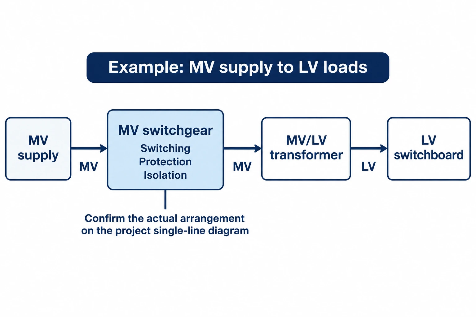
Other projects have ring supplies, several transformers, generators or multiple outgoing feeders. These arrangements change the required switching functions and protection scheme.[3][5] Count functional circuits from the diagram before counting cabinets in a quotation.
Do not use the term alone as a purchasing specification. G&W Electric’s overview describes MV equipment in a 1–35 kV range. IEC 62271-200:2021, by contrast, covers specified AC metal-enclosed assemblies with rated voltages above 1 kV up to and including 52 kV.[1][2] The latter is the scope of a particular standard, not a universal definition of every MV product.
Specify the nominal system voltage, required equipment rated voltage, frequency and insulation levels separately. Ask the supplier to identify the applicable standard and edition. A description such as “MV panel” leaves too much open for technical acceptance.
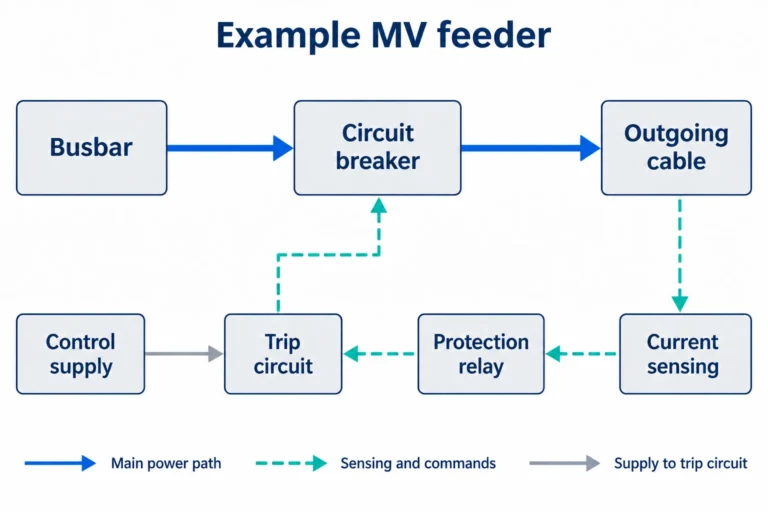
The required components depend on the circuit. A breaker-protected feeder commonly combines a circuit breaker, current measurement, protection relay, busbar connection, cable connection and control equipment.[1][4] Other arrangements use a coordinated switch-fuse combination rather than a breaker and relay.[3]
These functions must not be confused:
For a transformer feeder, ask how the protection coordinates with upstream and downstream devices and accommodates transformer energization. These are protection-study questions, not features that can be confirmed from the front-panel display.[4] The transformer specification checklist helps assemble the transformer-side inputs for that review.
“Air-insulated,” “vacuum” and “withdrawable” describe different aspects of equipment. Treating them as mutually exclusive types can lead to an incomplete enquiry.
Air-insulated, gas-insulated and solid-insulated designs describe insulation arrangements.[3] Vacuum describes the interruption medium of a switching device; ABB’s SafeRing/SafePlus catalogue, for example, includes vacuum circuit-breaker modules within a gas-insulated product family.[8]
Gas-insulated does not automatically mean SF6-insulated. ABB also identifies dry-air variants in its SafeRing/SafePlus range.[7] Ask which insulation medium and interrupting technology the offered model uses, rather than transferring a description from another series.
Compact ring main units suit defined distribution functions, while compartmented modular units support different single-line arrangements and layouts.[3] Begin with the number and type of required functions, provision for expansion, protection arrangement and cable interfaces. Then compare the proposed equipment layout.
A compact enclosure is only useful if the complete installation fits. Cable space, access and any specified pressure-relief arrangement remain part of the room design.[8]
Ask which compartments can be accessed and what must be de-energized for the intended maintenance task. IEC-based Loss of Service Continuity, or LSC, classification describes the extent to which other parts can remain energized when an accessible compartment is opened.[3][6] It is not a general permission to work on energized equipment.
The maintenance method also needs a drawing-level check: how a replaceable device is reached or removed, where it can be handled, and which adjacent equipment becomes unavailable. Request the manufacturer’s access and maintenance instructions before accepting the layout.
A compatible voltage rating does not establish a compatible cable connection. Confirm the cable construction and conductor size, number of cables per phase, terminal or bushing interface, and the termination kit accepted for that interface. ABB’s catalogue illustrates why this matters: it distinguishes bushing interfaces and cable-cover arrangements for different connection configurations.[8]
Ask for a sectional drawing showing the entry direction, termination position, supports and usable cable space. Compare it with the cable and accessory manufacturers’ requirements, including the installation envelope and bending radius. Where surge arresters or additional cables are required, check their space on the same drawing rather than assuming they will fit later.[8]
Put responsibilities in writing. Who supplies the cables and termination kits? Who installs them, performs site tests and confirms the completed connections? A switchgear supply quotation should not be read as an offer to supply cables or deliver the whole electrical installation unless that scope is expressly included.
Give the supplier the actual environment: indoor or outdoor location, ambient conditions, altitude, contamination and condensation exposure. The equipment must be assessed against its electrical and environmental service conditions.[3] “Indoor” alone does not describe a hot, damp or dusty room.
If internal arc classification is required, request the classification, fault current, duration, accessible sides and installation conditions for the offered configuration. ABB’s catalogue shows that pressure-relief arrangements, ceiling height, wall distances and floor fixing can be conditions of a particular tested arrangement.[8] Do not copy those dimensions to another model.
Also review the interlocking scheme and possible alternative supplies. A transformer connected to a generator or another source may need coordinated isolation across equipment boundaries.[5][6] Have the responsible engineer approve the arrangement; a door interlock is not a complete site isolation procedure.
Send the same technical baseline to each bidder. The checklist below combines project inputs with the evidence needed to assess the offered assembly.[3][5][8]
| RFQ item | Information to request or confirm |
|---|---|
| Network and circuit duties | Single-line diagram; incoming and outgoing functions; source arrangements; transformer or other load data; expansion requirements. |
| Voltage and insulation | Nominal system voltage; equipment rated voltage; frequency; required insulation levels; applicable standards and editions. |
| Current and fault duties | Continuous current by circuit; prospective fault level; required short-time withstand current and duration; peak withstand and applicable making/breaking duties. |
| Protection and control | Protection functions; relay and sensor/CT arrangement; coordination responsibilities; control supply; metering, communications and interlocks. |
| Installation and cables | Environmental conditions; general arrangement; access and handling space; cable entries, interfaces and termination requirements; earthing connections. |
| Verification and acceptance | Evidence applicable to the proposed assembly; routine-test documentation; agreed factory/site acceptance checks; internal arc evidence where specified. |
| Supply and maintenance scope | Included devices and accessories; cables/terminations included or excluded; installation and commissioning responsibilities; manuals, spares and maintenance access. |
Compare offers only after the technical requirements, installation interfaces and documentary evidence have been reconciled.
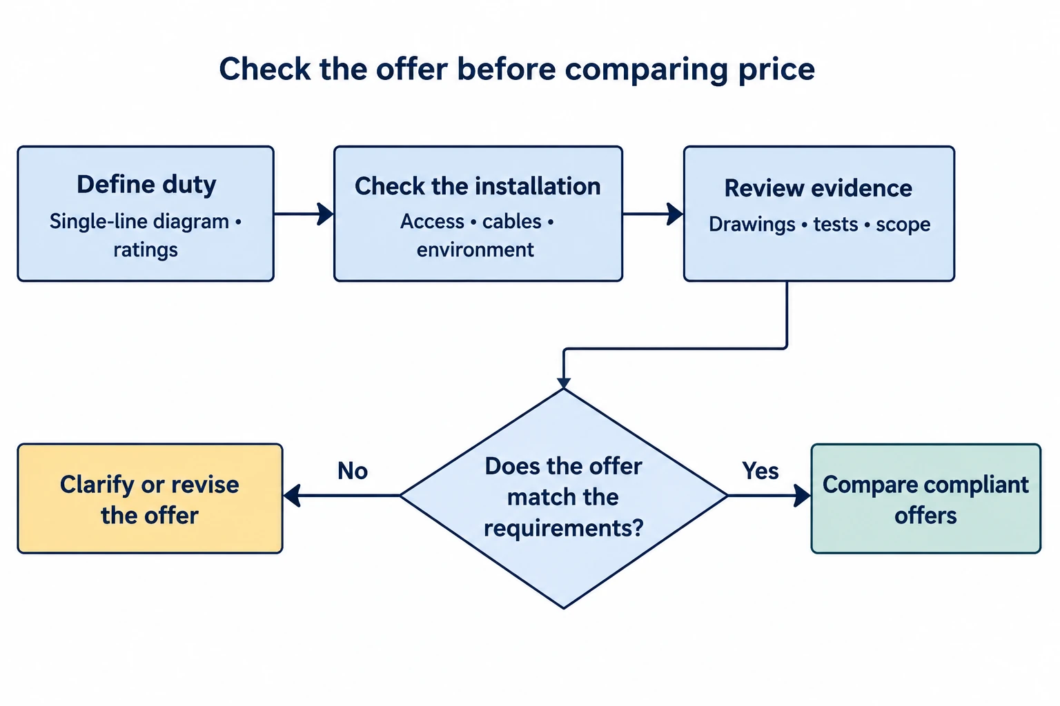
A single “kA” figure is not enough: short-time withstand includes a duration, while a device’s breaking duty answers a different question.[8] Likewise, a test report should be checked for applicability to the offered assembly, not accepted merely because its cover shows the same manufacturer’s name.
For an HJD enquiry, send the single-line diagram and this checklist, and request a written response identifying the proposed configuration, deviations and supply exclusions. Leave unresolved requirements visible until the responsible parties agree them.
No. Vacuum identifies the interrupting medium of the switching device, not necessarily the insulation around the assembly’s other live parts. Check the insulation system and the interrupting device separately.[8]