Request a Quote
Share your product list, technical ratings, quantity and delivery destination.
Understand grounding and earthing switch functions, their difference from disconnectors, and the ratings, interfaces and interlocks to check before purchase.
A grounding switch connects a defined part of an electrical circuit to earth. IEC terminology calls it an earthing switch: a mechanical switching device that can withstand specified short-circuit conditions but is not required to carry the circuit’s normal operating current.[1] Its purpose differs from that of a disconnector, which provides an isolating distance when open.[2]
For procurement, establish which circuit section needs earthing, then check the switch’s fault duties, installation interfaces and interlocks. A matching voltage label alone does not establish that a replacement device will fit or perform the required duty.
This guide uses the two terms for the same earthing function. The name on an enquiry is less important than the device description, applicable standard and proposed installation.
IEC 62271-102:2018+AMD1:2022 covers AC disconnectors and earthing switches for indoor and outdoor installations above 1,000 V, at service frequencies up to and including 60 Hz.[3] That scope does not mean every product is suitable for both environments. Ask the supplier to identify the standard and edition applicable to the offered model, together with its service conditions.
Keep the enquiry specific. “Grounding equipment” could describe a much wider package; state that you are requesting an earthing switch for a particular circuit or switchgear assembly.
A disconnector establishes the specified isolating distance in its open position. Its defined switching duties are limited; it should not be treated as a general-purpose load-interrupting device.[2] An earthing switch provides the connection between the selected circuit section and earth.[1]
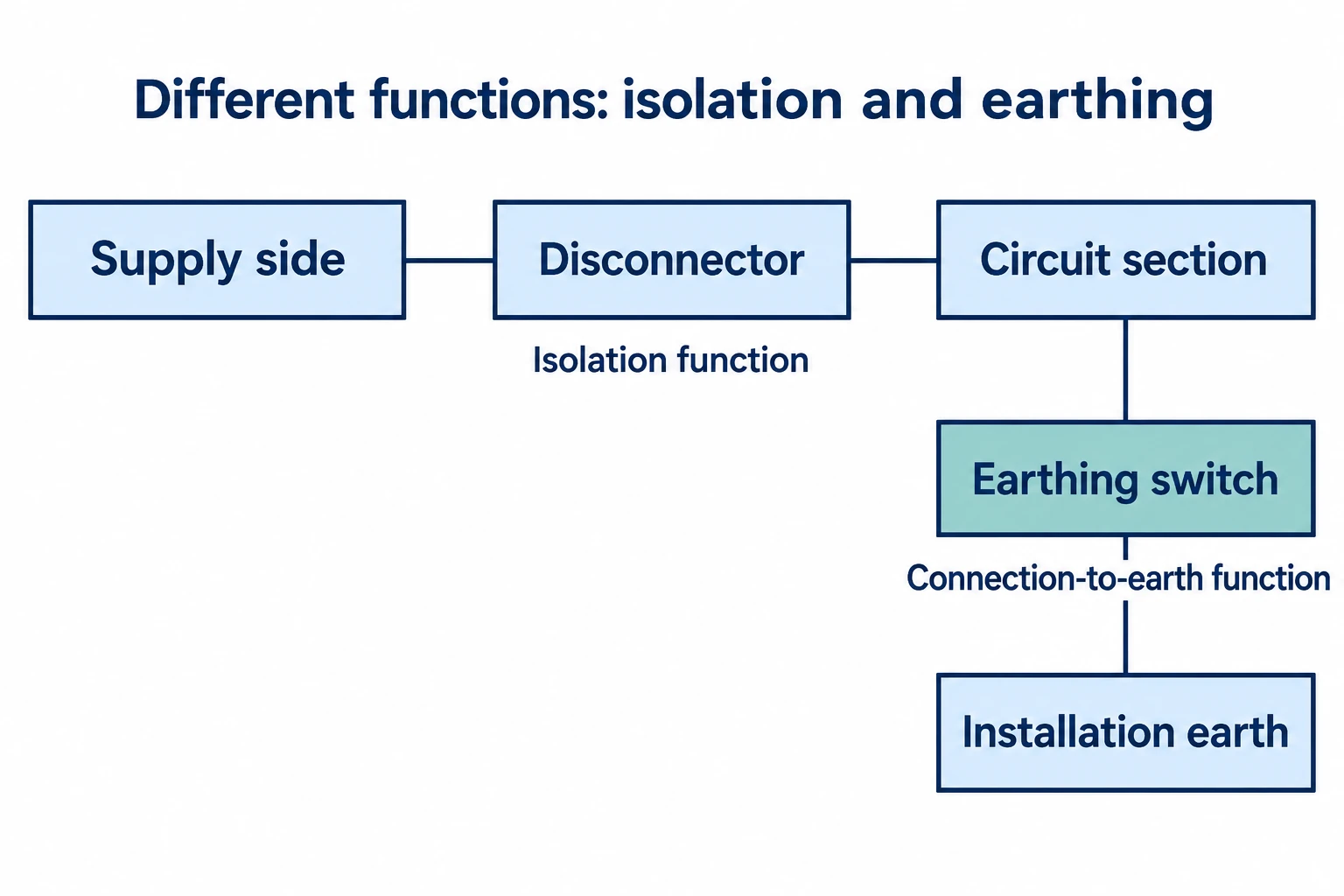
These functions may be provided by separate devices or combined within equipment that has several switching functions. IEC 62271-102 expressly includes devices with disconnecting or earthing functions alongside other functions.[3] Whatever the packaging, the drawing should identify exactly what is isolated and what is earthed.
For example, specify whether the required earthing point serves a cable connection, a busbar section or another defined part of the circuit. Then check that location against the intended maintenance boundary. Do not accept “earth switch included” as a complete description when the project drawing leaves that boundary unclear.
An earthing-switch position indicator does not, by itself, establish that all sources are isolated or that absence of voltage has been verified. The approved safety procedure and equipment instructions must address those conditions; the interlocking scheme is only part of that arrangement.[5]
A short-time withstand requirement concerns the current the closed path can withstand for a specified duration. A short-circuit making requirement concerns closing onto a short circuit. IEC’s definition says an earthing switch may have short-circuit making capacity, so that capability cannot be assumed for every device.[1]
Read the short-time current together with its duration, and verify short-circuit making capability separately.
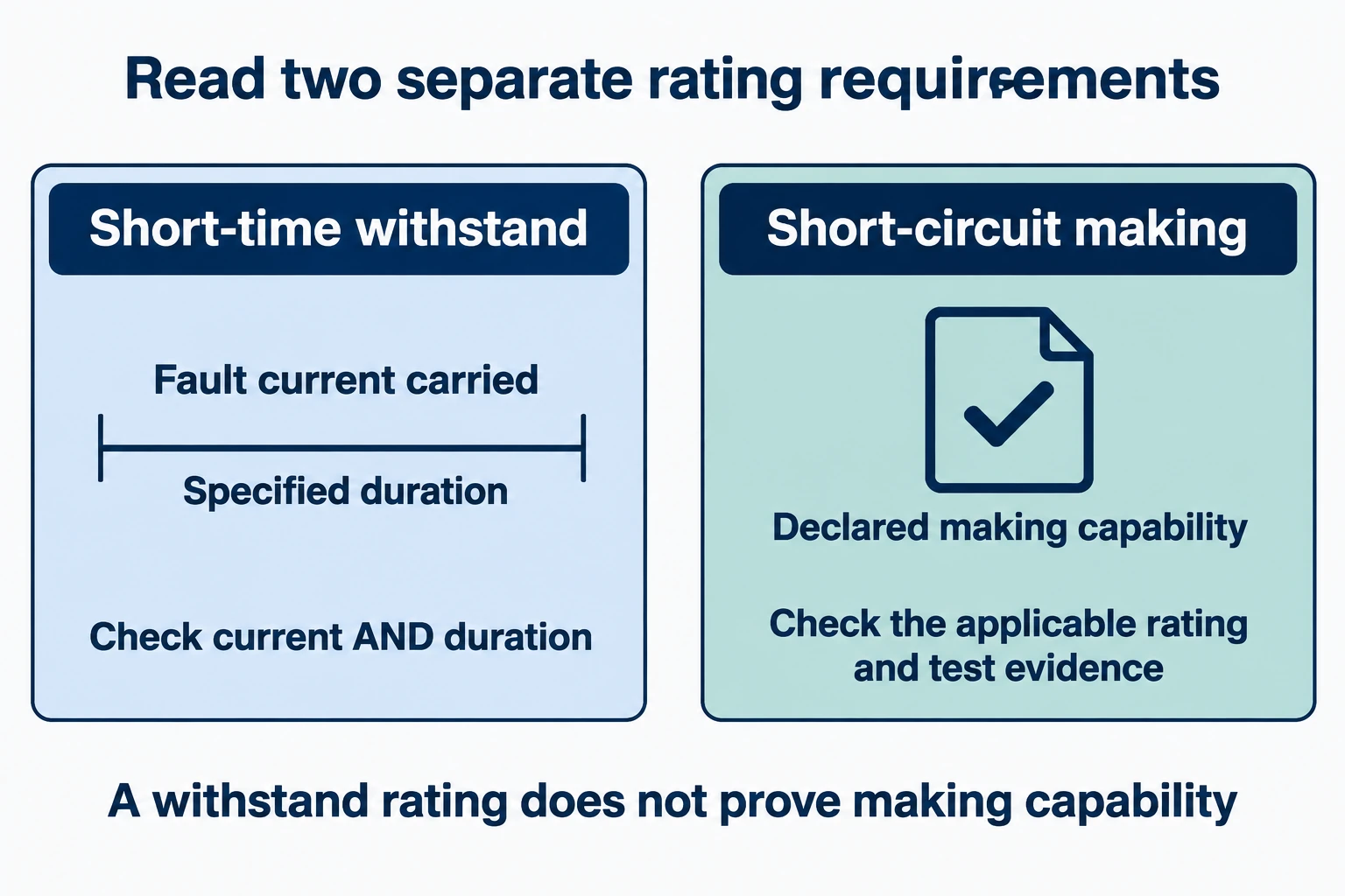
ABB’s EK6 manual illustrates the distinction with separate columns for rated short-time current, short-circuit duration and short-circuit making current.[4] It is a model-specific example, not a rating recommendation for another switch.
When reviewing an offer:
Making capacity is an equipment rating, not permission to use the switch as an alternative to isolation, voltage verification or the approved work procedure. Nor does a making rating establish a fault-breaking capability. The enquiry must distinguish the duties the device actually performs.[1][3]
The moving part, fixed contacts, operating mechanism and earth connection need to work as a complete arrangement. A switch body that looks similar can still have incompatible mounting or contact positions.
ABB’s EK6 manual provides a concrete example: the active part and corresponding earthing contacts are supplied for integration into a panel, with contact positions set by dimensional drawings. The manual also describes connections from the moving assembly to earth through copper conductors.[4] Those details show why a component catalogue cannot replace the installation drawing.
Request the mounting drawing, pole spacing, fixed-contact arrangement, operating-shaft interface and the specified connection to the installation earth. Identify which parts come with the offer and which must be provided by the panel builder. For a retrofit, obtain the existing assembly details before approving a substitute.
Also confirm operating conditions and access. An indoor device does not become an outdoor-rated product simply because it is placed inside a cabinet; the proposed installation still needs assessment against the manufacturer’s environmental limits. The EK6 manual, for instance, explicitly limits the described devices to stated indoor conditions.[4]
Interlocks constrain switching or access according to the equipment arrangement. Schneider Electric describes both mechanical and electrical interlocks, including relationships between an earthing switch and associated switching devices.[5]
Ask for an interlocking diagram or cause-and-effect description that identifies permitted states, blocked actions and the equipment involved. If a transformer, generator or another source affects the same work boundary, include it in the review. A local mechanism cannot establish the state of an unrelated supply unless the required coordination is actually provided.[5]
For motor-operated equipment, define the control supply, local/remote selection, auxiliary contacts and required position signals. Ask how the indicated state relates to the switching device’s actual position. Position indication and interlocking are both addressed in the IEC standard’s published revision summary.[3]
Keep these as design and acceptance questions. The final operating instructions must come from the approved equipment documentation and site procedure, rather than a generic sequence copied into the purchase order.
The switch provides a connection for a defined circuit section. It relies on a connection to the installation earth; the EK6 construction example makes that physical interface explicit.[1][4]
The wider substation grounding design is a separate engineering scope. Buying the switch does not settle the grounding network layout, conductor connections or the site’s electrical-safety assessment. Record who is responsible for the switch-to-earth interface and who approves the installation grounding design.
If the request is for a switch only, keep grounding-network design, construction and testing outside the assumed supply scope unless they are expressly included. This prevents a component quotation from being mistaken for a complete substation service package.
Provide the single-line diagram and the relevant assembly drawing, then ask every bidder to respond to the same requirements. The checklist below translates the device, rating and installation distinctions into procurement questions.[1][3][4]
| RFQ item | What to specify or request |
|---|---|
| Circuit function and boundary | Identify the circuit section to be earthed, its relationship to isolating devices, and any alternative sources relevant to the work boundary. |
| Voltage and environment | System and equipment voltage requirements, insulation requirements, frequency, indoor/outdoor installation and actual service conditions. |
| Fault duties | Required short-time current and duration; applicable peak withstand and making duties; clearly labelled RMS/peak values and evidence. |
| Mechanical interfaces | Assembly drawing, pole spacing, mounting and fixed-contact positions, operating shaft, access and replacement constraints. |
| Earthing connection | Connection points, conductor/interface requirements, supplied parts and responsibility for integration with the installation earth. |
| Operation and interlocks | Manual or motor operation, control supply where applicable, interlocking scheme, position indication and local/remote requirements. |
| Documentation and scope | Applicable standards and editions, configuration-relevant test evidence, installation/maintenance instructions, acceptance checks and exclusions. |
For a transformer-bay enquiry, collect the transformer-side inputs as well; the transformer specification checklist can help keep that information together.
Send HJD the circuit and assembly drawings with the required duties, then request a written response identifying the proposed configuration, interfaces and exclusions. Resolve those points before treating offers as technically comparable.
Voltage alone is insufficient. Check fault duties, dimensions, contact and operating interfaces, the earth connection, interlocks and the suitability of the resulting assembly. Manufacturer drawings and installation requirements are essential to that review.[4]
Only if the quotation expressly includes that wider scope. Ask who supplies and connects the switch’s earth interface and who is responsible for the installation grounding design, construction and acceptance testing. Keep those responsibilities visible in the purchase specification.