Request a Quote
Share your product list, technical ratings, quantity and delivery destination.
Learn what a fuse cutout does, how its fuse link and holder work, and which load-switching, rating and compatibility checks matter before purchase.
A fuse cutout is a protective assembly used in electrical distribution systems. In a common drop-out expulsion design, a replaceable fuse link sits inside a fuseholder supported by an insulator and contacts. When the fuse operates, it interrupts the faulted circuit; the holder then drops open to leave a visible break.[1][2]
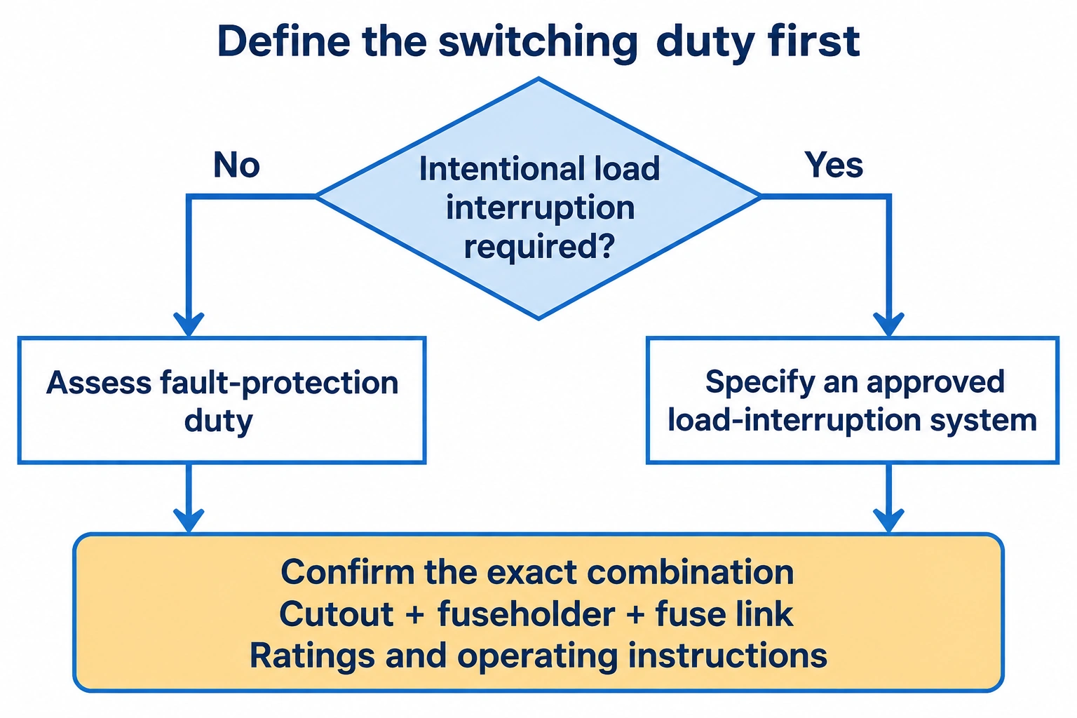
For selection, separate fault protection from intentional load switching. An ordinary cutout’s fault rating does not establish load-switching capability; that requires an approved arrangement.[4]
Typical applications include transformer and line protection on overhead distribution networks.[3]
This article covers the conventional expulsion type. Current-limiting fuses, including some dropout designs, use a different interruption principle and need their own selection review.[1]
The insulator supports the fixed contact assembly, while the fuseholder engages the upper contact and a lower hinge. The hinge retains the holder as it pivots into the open position.[2]
The fuse link is the replaceable protective element inside that assembly. Its ampere rating and time-current characteristic determine its response to current; the holder has its own permissible link range and equipment ratings.[7][8]
Keep these items separate in an enquiry. “Fuse cutout” may mean the complete assembly, a replacement fuseholder or a fuse link to different sellers. State what is required, including mounting hardware and terminals. A current product sheet can list a cutout with no bracket, so mounting hardware should be confirmed explicitly.[8]
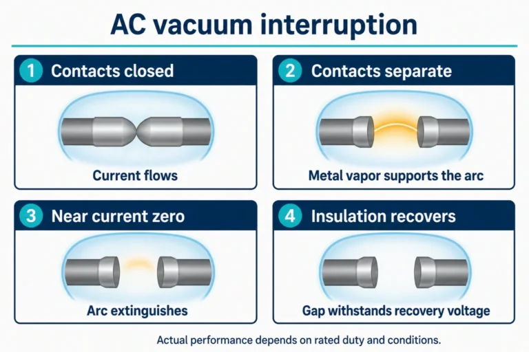
Fault current heats the fusible element until it melts and an arc forms. The expulsion fuse interrupts at an AC current zero rather than forcing the current to zero early, as a current-limiting fuse does.[1] The fuseholder and its associated mechanism participate in interruption and dropout, so they form part of the protective assembly.[2]
After dropout, the fuseholder remains supported at the lower hinge and no longer engages the upper contact.[2]
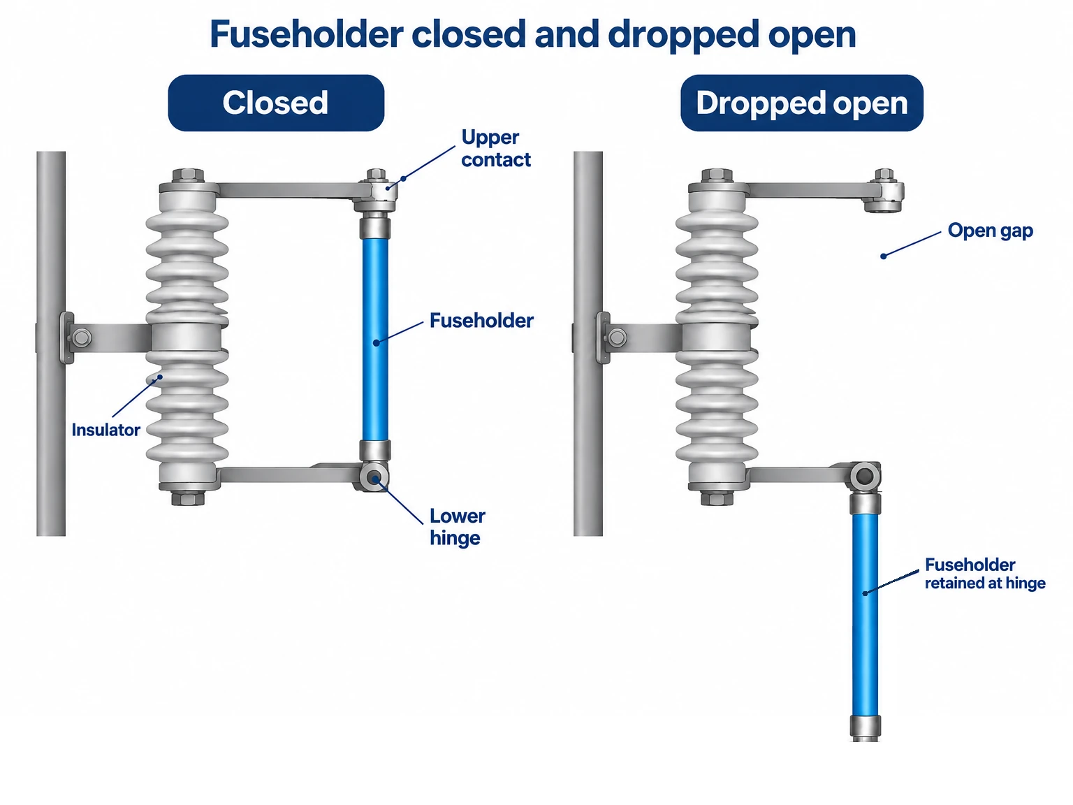
The open gap identifies the holder position, not the electrical condition of every component. S&C requires equipment to be de-energized, tested and grounded before it is treated as safe for work.[4]
For maintenance planning, request the manufacturer’s inspection and re-fusing instructions with the equipment. The protection investigation and the condition of the assembly belong in that process; replacing the link is not a diagnosis of the fault.
If intentional load interruption is required, specify an approved load-interruption system before comparing cutout models. Confirm the complete cutout, fuseholder and fuse-link combination, its ratings and the applicable operating instructions.
The following distinctions matter when reviewing a catalogue:
These are different operating arrangements. Request the rated load-switching duty, compatible parts and manufacturer’s method for the proposed model. Do not infer them from a pull-ring, a product photograph or a short-circuit rating.
A cutout’s continuous-current rating, its fuse-link range and its interrupting-current rating describe different limits. Hubbell’s CP720213E sheet lists these separately.[8] The holder rating alone does not tell you which link will protect the connected equipment.
Start with the maximum system voltage, network grounding arrangement and available fault current at the installation point. Match the voltage application and fault-duty requirements to the exact cutout and holder. Where a catalogue gives a slant voltage rating, confirm its stated phase-to-ground and phase-to-phase application limits.[5]
Then review the fuse link’s time-current curves. S&C publishes separate minimum-melting and total-clearing curves for its links.[3] Use the relevant curves for coordination with upstream and downstream devices, including the equipment’s expected load and energization conditions. Account for the curve assumptions: S&C’s K-speed documentation notes that preloading reduces melting time.[7]
For replacement parts, require the original model or a documented compatible combination. In its Type XS instructions, S&C ties certain interrupting ratings to an arc-shortening rod and specifies restrictions on mixed assemblies.[4] A tube that appears to fit does not establish the rating of the completed device.
Give suppliers enough information to identify both the assembly and the protective link. The following checklist keeps the electrical duty, mechanical fit and supply scope visible during quotation review.
| Information to provide | What to ask the supplier to confirm |
|---|---|
| Maximum system voltage, frequency and grounding arrangement | Applicable voltage rating, insulation level and restrictions for the proposed model. |
| Available fault current at the installation point | Interrupting rating of the complete cutout, holder and link arrangement, with its stated rating basis. |
| Connected equipment, normal load and energization conditions | Proposed fuse-link rating, characteristic curves and coordination inputs. |
| Whether intentional load interruption is required | Approved switching arrangement, compatible parts, load duty and operating instructions. |
| Existing model and replacement scope | Exact replacement identification and documented compatibility of the parts being supplied. |
| Installation environment, mounting and conductor details | Insulator material, mounting hardware, terminal suitability and required installation provisions. |
| Required documents and spare parts | Drawings, applicable test evidence, link curves, instructions and the parts included or excluded. |
For a transformer application, the transformer specification checklist can help organize the connected equipment’s data. The fuse-link choice still needs a protection-coordination review.
Request a returned technical schedule that identifies the fuse-cutout assembly, fuseholder and fuse link separately. Ask the supplier to mark any missing system information and deviations from the enquiry. This makes it possible to compare the proposed protection arrangement before accepting the quotation.
No. The holder’s current rating and its permitted fuse-link range are separate entries in the equipment specification.[8] Select the link from the protection requirements, then confirm that the complete combination is approved.
Use the original model identification and the manufacturer’s compatibility documentation. Similar-looking holders can have different ratings or construction requirements. S&C’s instructions explicitly address compatibility and the rating implications of certain replacement combinations.[4]