Request a Quote
Share your product list, technical ratings, quantity and delivery destination.
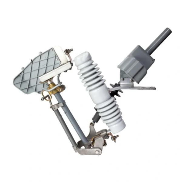
A 12 kV motor-operated drop-out fuse with a dedicated arc-control device. Select the 100 A or 200 A version, porcelain or composite silicone-rubber insulation, and a 12 V DC or 24 V DC motor for the required switching duty.
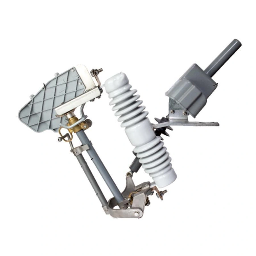
A 12 kV motor-operated drop-out fuse with an arc-control device. Choose the 100 A or 200 A version, porcelain or composite insulation, and a 12 V DC or 24 V DC motor.
The fuse link provides overcurrent protection. A DC motor operates the mechanism, while a separate arc-control device forms part of the load-type construction.
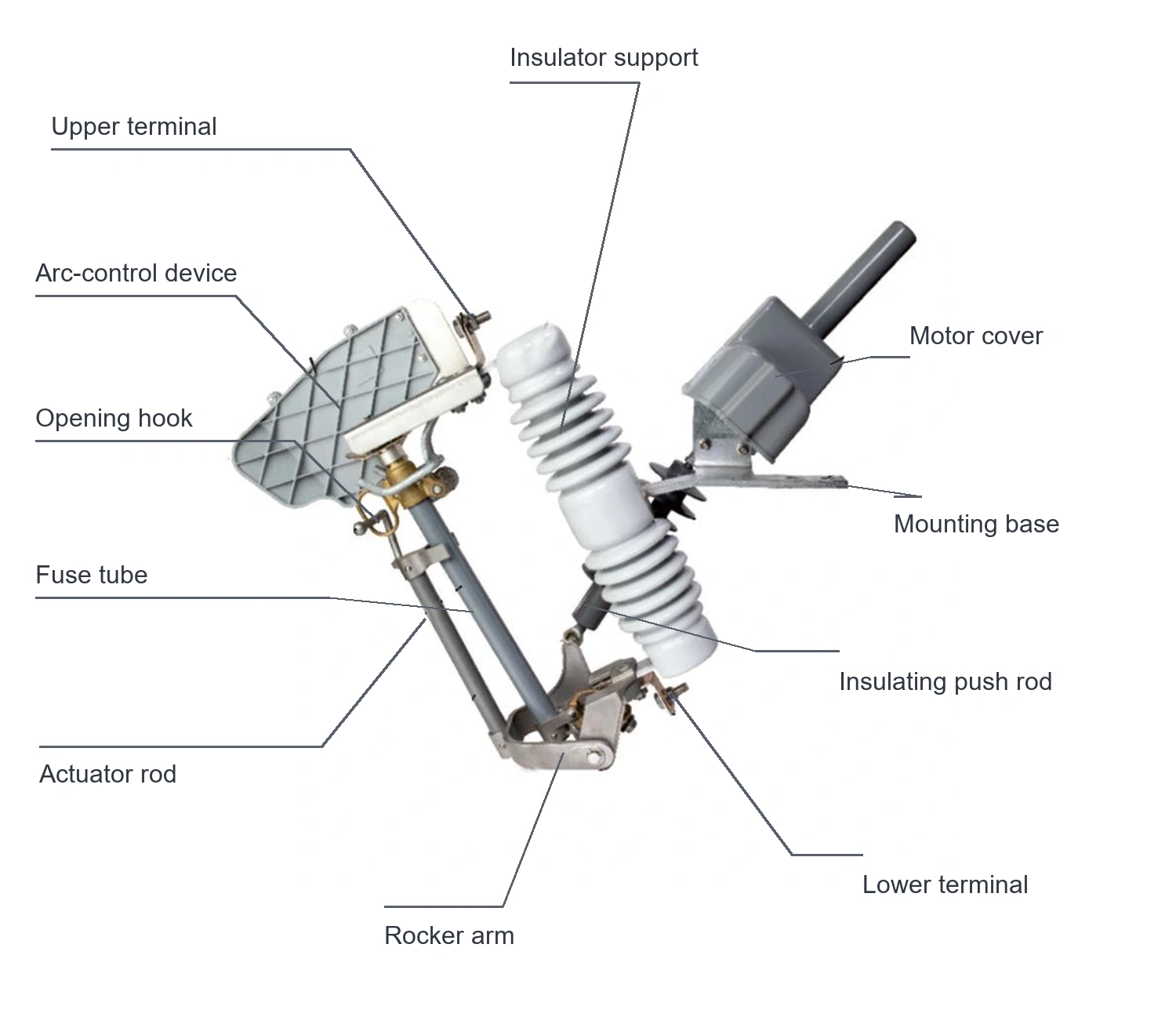
12 kV load-type component reference; not an installation drawing.
The load-type assembly includes an arc-control device at the upper contact area.
Load-switching duty is specified for the complete assembly. The listed 12.5 kA and 16 kA values are fuse breaking-current ratings.
The catalog lists standard and load-type motorized versions. The load type adds an arc-control device.
On smaller screens, scroll the table sideways to compare both options.
| What to compare | Standard motorized type | Motorized load type |
|---|---|---|
| Product designation | Electric drop-out fuse | Electric drop-out fuse, load type |
| Arc-control device | Not shown on the standard-type drawing | Shown at the upper contact area |
| Rated voltage and current | 12 kV; 100 A / 200 A | 12 kV; 100 A / 200 A |
| Insulation and minimum creepage | Porcelain or composite silicone rubber; 380 mm | Porcelain or composite silicone rubber; 380 mm |
| Motor supply | 12 V DC / 24 V DC | 12 V DC / 24 V DC |
The fuse breaking-current rating and the permitted load-switching duty are separate specifications. Use the operating instructions and test scope for the selected assembly.
| Electrical parameter | Specification |
|---|---|
| Product series | 12 kV load-type motor-operated drop-out fuse |
| Rated voltage | 12 kV |
| Rated current options | 100 A / 200 A |
| Listed fuse breaking-current ratings | 12.5 kA / 16 kA |
| Current / breaking-rating combinations | 100 A / 12.5 kA; 200 A / 16 kA |
| Insulation options | Porcelain (C) / composite silicone rubber (H) |
| Minimum creepage distance | 380 mm |
| Load-switching duty | Defined for the selected assembly; the catalog does not list a separate numerical load-switching-current rating |
Select the fuse link and coordinate it with the circuit protection. The model-code diagram pairs 100 A with 12.5 kA and 200 A with 16 kA.
The arc-control device is part of the load-type design. Use the permitted switching duty and operating procedure for the ordered unit.
After the fuse operates, replace the specified fuse link and check the fault before restoring service. Select control commands and interlocks with the motor and controller.
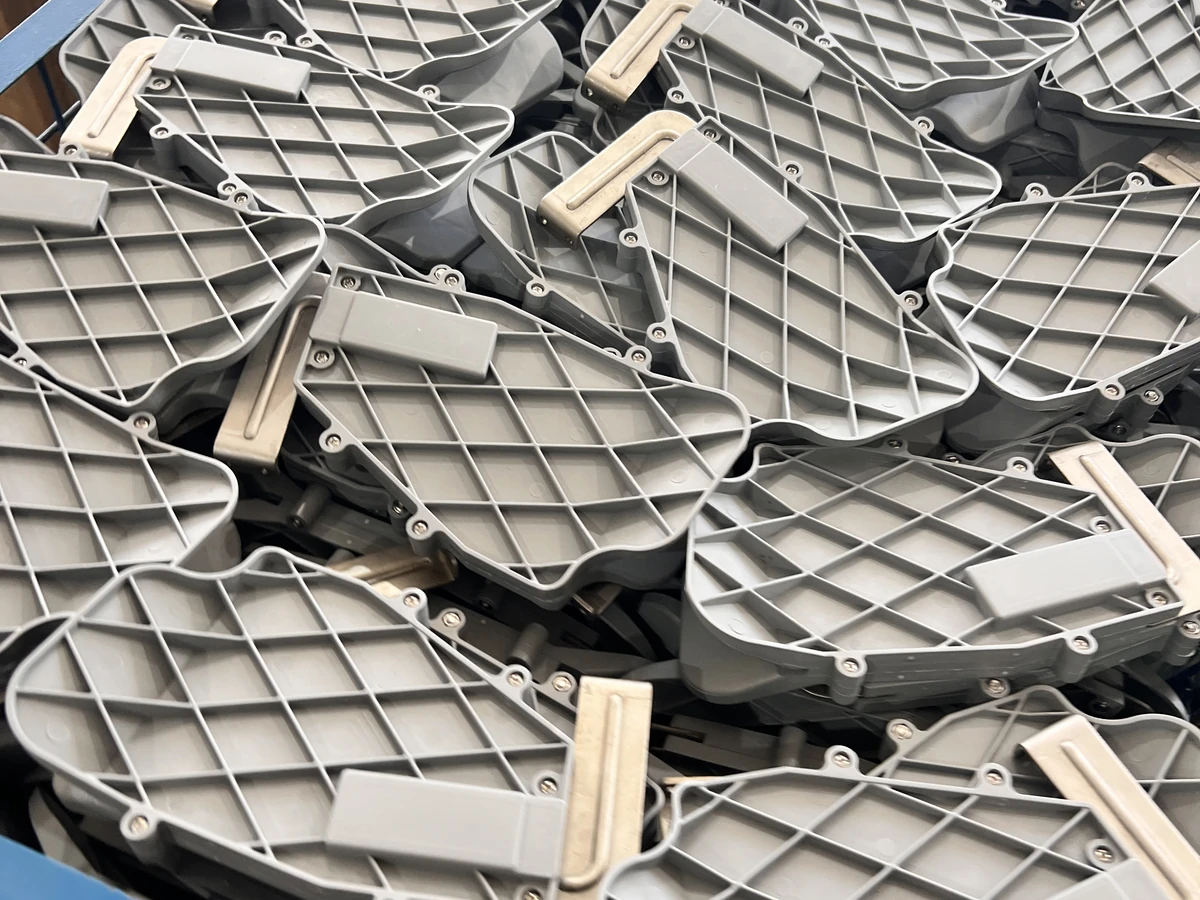
Arc-control device components, shown as a construction reference.
Select the electrical arrangement and interfaces for the intended duty.
| Selection item | Specification / requirement |
|---|---|
| Motor voltage options | 12 V DC / 24 V DC |
| Fuse assembly | 12 kV, 100 A or 200 A, with C or H insulation |
| Operating controls | Controller and operating interface selected for the project |
| Fuse links | Specify the required link and protection coordination |
| Accessories | Power supply, wiring, mounting hardware and operating tools as ordered |
| System interfaces | Integration requirements specified separately |
Select the controller, power supply and operating interface for the motor. Communication functions require their own agreed specification.
| Interface | Reference / requirement | Selection note |
|---|---|---|
| Fuse assembly | Selected outline drawing required | Use the drawing for the ordered 12 kV version |
| Mounting base | Confirm support and hole pattern | Check phase spacing and conductor loading |
| Arc-control device and movement | Allow the full operating envelope | Keep installation clearances per the approved drawing |
| Terminals | Confirm conductor and connector interfaces | Specify conductor material, size and connection arrangement |
| Control equipment | Confirm position and cable route | Coordinate the selected DC supply and service access |
Use the approved outline and terminal drawing for the selected 12 kV version.
Check the support, terminals, arc-control device clearance and complete movement envelope. Verify the selected 12 V DC or 24 V DC supply, wiring, controls and operating sequence against the approved documents.
| Condition | Requirement / project input |
|---|---|
| Installation | Outdoor |
| Ambient temperature | -30 to +45 C |
| Altitude | Up to 3,000 m |
| Radial ice thickness | 2 mm |
| Additional site inputs | Provide pollution exposure, wind, corrosion conditions and installation requirements |
Include pollution, wind and corrosion exposure with the site information. State any conditions outside these ranges.
Specify the required current and fuse protection for the branch, together with the permitted switching duty.
Check the support, terminal positions and space for the added arc-control device against the existing installation.
Select the 12 V DC or 24 V DC drive and the controller, power supply and operating interface used at the site.
Selection example for project planning.
The branch requires fuse protection and a motor-operated mechanism with a defined load-switching duty. Select the current version and fuse link for the circuit.
Match the DC supply and controls to the motor. Check the mounting points, terminals and arc-control device clearance, then review the permitted switching duty for the complete assembly.
Production follows the approved drawings, the applicable product standards and the agreed inspection plan.
We can adjust the configuration for your operating environment and provide neutral packaging or your logo. Send the site conditions and branding requirements with your enquiry.
Incoming components, production work and finished units are checked against the requirements for the ordered configuration.
Incoming materials and components are checked against the approved specifications before production.
Assemblies and semi-finished components are inspected at the relevant production stages.
Finished equipment and release records are checked against the approved order requirements.
Factory acceptance testing (FAT). Every unit undergoes FAT before packing. Test items and acceptance criteria follow the product and approved configuration. FAT reports and packing inspection photos accompany the shipment. Factory attendance, video witnessing or independent inspection can be arranged with an agreed scope and schedule.
Explore related guides for product selection, specifications and project planning.
Review components, ratings and fuse-link compatibility.
The load-type motorized version includes an arc-control device. The standard motorized-type drawing does not show that device.
No. The catalogue lists them under breaking-current capacity for the fuse. It does not state a separate numerical load-switching-current rating. Confirm the required switching duty for the proposed device.
The fuse cutout ratings and switching guide separates fuse interruption from load-switching duty.
The model diagram shows 100 A with a 12.5 kA fuse breaking rating, and 200 A with a 16 kA rating. C denotes porcelain insulation and H denotes composite silicone rubber. Confirm the full model code for the ordered unit.
The motor options are 12 V DC and 24 V DC. Specify the controller, power supply and operating interface in the enquiry. No communication protocol, telemetry function or automatic-reclosing function is defined on this product catalogue page.
Send the project location, system voltage, required current, quantity, insulation preference and motor voltage. Identify the required switching duty and confirm the fuse links, controller, power supply, wiring, mounting hardware and document scope with the quotation.