Request a Quote
Share your product list, technical ratings, quantity and delivery destination.
Match the transformer to the available supply, load arrangement, and installation limits. Compare phase loading, winding connections, banked units, and the data needed for an RFQ.
Choose a single-phase or three-phase transformer by matching the available supply, the loads it must serve, and the required secondary voltage. Phase count alone does not determine capacity or efficiency. A useful comparison also checks total kVA, winding connections, neutral requirements, and how the loads will be distributed. An ordinary transformer changes voltage; it cannot turn a single-phase source into a balanced three-phase supply.
Record the incoming voltage, frequency, and phase arrangement before comparing transformer quotations. Then separate the load schedule into single-phase and three-phase equipment. A workshop with a three-phase motor and several single-phase auxiliary loads needs a different supply arrangement from a building containing only single-phase loads, even if their total kVA is similar.
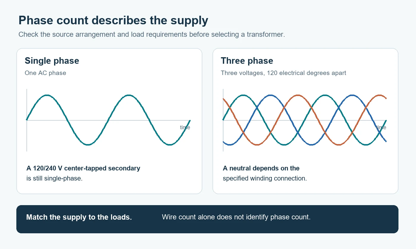
Do not identify phase count by counting wires. A center-tapped 120/240 V supply is single-phase, although it has two line conductors and a neutral. A three-phase system has three alternating voltages displaced from one another by 120 electrical degrees. It may have a neutral, depending on the connection. HPS distinguishes single-phase and three-phase systems by their electrical arrangement rather than terminal count.
When the site has only single-phase power but the equipment requires three-phase power, establish the conversion solution before specifying a transformer. HPS confirms that a transformer alone cannot perform that phase conversion. Quoting a three-phase transformer without resolving its source supply leaves the central project requirement unanswered.
| Selection factor | Single-phase transformer | Three-phase transformer or bank |
|---|---|---|
| Electrical duty | Transforms power for a single-phase circuit. | Transforms power for a three-phase circuit. |
| Secondary loads | Single-phase loads at the specified output voltage. | Three-phase loads; suitable connections can also supply single-phase loads. |
| Neutral requirement | May require a center-tapped secondary or another specified arrangement. | Depends on the secondary connection and whether a neutral is brought out. |
| Loading check | Total kVA and loading of each section of a split secondary. | Total kVA, phase loading, and the distribution of single-phase loads. |
| Construction choice | One single-phase unit. | One three-phase assembly or a suitably connected bank of single-phase units. |
| Efficiency comparison | Compare documented losses at the relevant duty. | Use the same loss and duty comparison; phase count is not an efficiency rating. |
The table is a starting point for the specification. The supplier still needs the actual primary and secondary voltage arrangement. “480 V to 208 V” omits whether the secondary must also serve line-to-neutral loads, a detail that can change the winding connection and terminals required.
Transformer nameplate kVA describes apparent power. It is not the same as the connected load’s kW, and a three-phase transformer’s stated total kVA is not a per-phase rating. Convert the load schedule on a consistent basis before comparing quotations. The transformer sizing guide covers the capacity calculation separately.
For a single-phase circuit, current is total kVA × 1,000 ÷ voltage. For a balanced three-phase circuit, line current is total kVA × 1,000 ÷ (√3 × line-to-line voltage). These are the single-phase and three-phase relationships published by HPS.
For example, assume 100 kVA at 480 V, with a balanced load in the three-phase case. Single-phase current is about 208 A; three-phase line current is about 120 A. Both cases transfer the same total apparent power. The lower line current in the three-phase example follows from power being carried across three phases; it is not evidence of lower transformer losses.
Use the voltage associated with the calculation. Substituting a line-to-neutral voltage into the three-phase formula while retaining √3 produces an incorrect current. For a mixed load schedule, also examine each phase rather than relying only on the total.
Specify primary and secondary connections along with the voltage. On a three-phase transformer, delta and wye connections give different terminal arrangements and neutral options. Where the project specifies a vector group or phase displacement, include that designation in the inquiry rather than asking the supplier to infer it from the voltage ratio.
Consider a project requiring both 208 V three-phase loads and 120 V single-phase loads. A suitable 208Y/120 V secondary provides the intended line-to-line and line-to-neutral voltages. The inquiry must identify both duties and the neutral requirement. “208 V secondary” by itself does not communicate the complete load arrangement.
Distribute single-phase loads across the phases and identify their expected operating pattern. A total below the transformer rating can conceal a heavily loaded winding. HPS explains that unbalanced loading can create voltage imbalance, additional losses, and neutral current. For a center-tapped single-phase secondary, check the loading of both halves for the same reason: the total alone is incomplete.
A useful load schedule therefore shows voltage, phase, running demand, and which loads operate together. Keep motor starting and nonlinear-load requirements visible instead of burying them inside a single total.
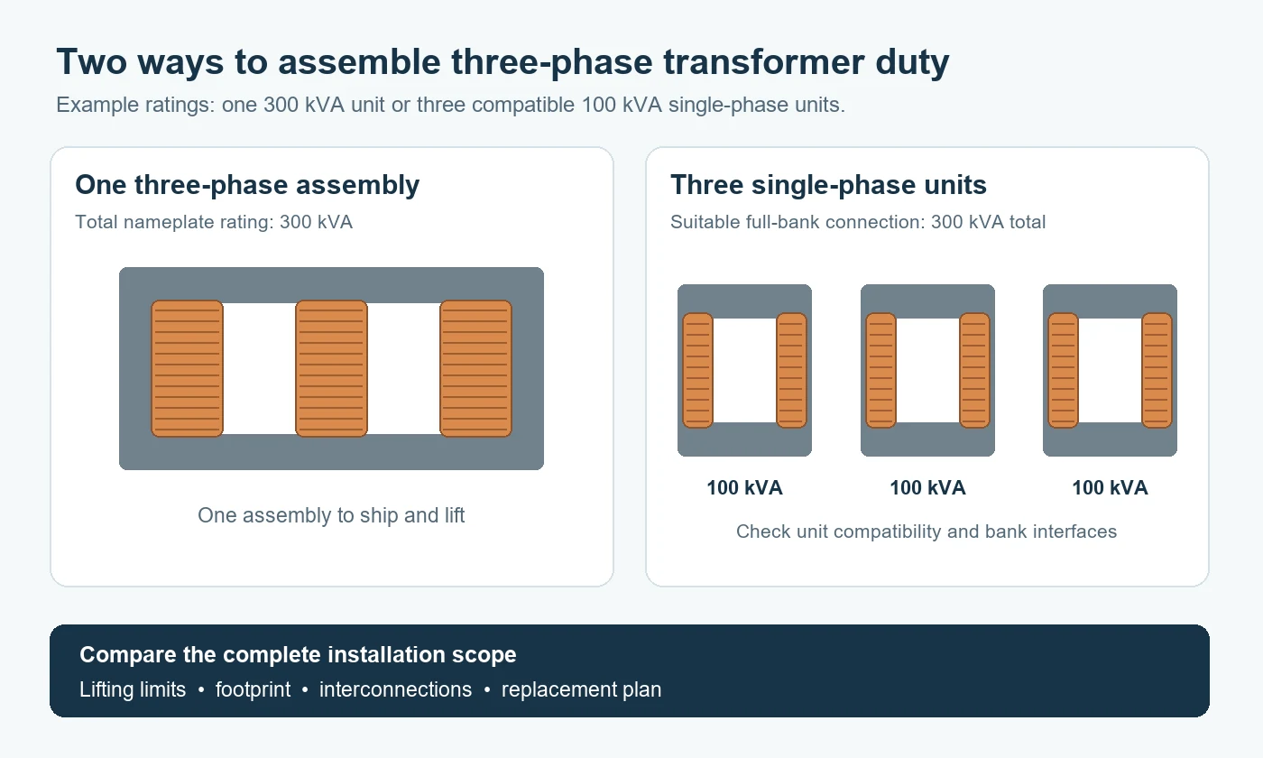
Three-phase service can use one three-phase transformer assembly or a properly designed bank of single-phase units. The choice affects shipment, lifting, installation interfaces, and replacement planning. HPS notes that banked single-phase transformers can help where individual shipping or lifting size is a constraint.
For a full three-phase bank of three compatible, equal-rated 100 kVA units, a suitable connection can provide 300 kVA total. Specify the complete bank duty, not just “three 100 kVA transformers.” The supplier must confirm the unit ratings, connections, and assembled-bank requirements together.
Compare the practical scope on each quotation. One three-phase assembly and three separate units do not necessarily include the same interconnections, mounting arrangement, terminal protection, or installation work. Ask who supplies each item and which drawings define the finished arrangement.
Replacement planning also needs a defined operating case. Removing one unit does not leave the original bank’s full rating available. If continued service during a unit outage is required, request the permitted configuration, remaining capacity, and load restrictions as a separate engineered proposal. This makes the continuity requirement measurable instead of relying on the word “redundant.”
A single-phase versus three-phase comparison should use supplier loss data for the actual designs. No-load losses occur when the transformer is energized without a secondary load. Load losses include winding resistance and stray losses associated with load current.
Ask for the stated test conditions, rated-load losses, no-load losses, and the loading point used for any efficiency figure. Then compare the operating profile: a transformer energized continuously at light load presents a different loss-cost calculation from one running heavily loaded for a short shift.
A price comparison that combines different kVA ratings, temperature conditions, or loading assumptions will obscure the trade-off. Put those conditions alongside the numbers. The transformer losses and efficiency guide explains how to organize this part of the evaluation.
Once the electrical arrangement is clear, add the installation limits that can reject an otherwise suitable design: delivery access, maximum lifting mass, available footprint, ventilation space, and the intended indoor or outdoor location. For replacement work, include the existing nameplate and layout. A voltage-and-kVA request alone cannot establish mechanical fit.
| RFQ field | What to provide | What it resolves |
|---|---|---|
| Source supply | Available phases, voltage, frequency, and supply arrangement. | Whether the proposed transformer matches the incoming system. |
| Secondary duty | Required line-to-line and line-to-neutral voltages; load phases. | Output voltage arrangement and neutral needs. |
| Capacity and load schedule | Total kVA, phase allocation, simultaneous loads, and starting requirements. | Capacity selection and winding-loading checks. |
| Connections | Required winding connection, neutral terminals, and specified vector group. | Compatibility with the project electrical design. |
| Installation | Location, ambient conditions, dimensions, access, and lifting limits. | Construction and installation feasibility. |
| Comparison documents | Nameplate proposal, outline drawing, loss data, and project-required test records. | A quotation that can be checked against the same scope. |
State whether the request is for one three-phase assembly or a bank, and identify any permitted alternatives. If a field remains open, ask the supplier to list the assumption in the quotation. That keeps the proposed configuration visible during commercial comparison.
To discuss a project, send HJD the supply details, load schedule, and installation limits. Include the existing nameplate for a replacement and identify the documents required with the offer.
An ordinary transformer cannot create a balanced three-phase supply from a single-phase source. A project needing that conversion must specify suitable conversion equipment or a different supply arrangement before selecting any associated transformer.
No. Compare the designs’ no-load and load losses under the same stated conditions, then apply the expected loading and energized hours. Phase count by itself does not establish efficiency or annual energy cost.
A suitably specified bank can serve three-phase duty. The unit ratings, winding connections, complete-bank capacity, and installation interfaces need to match the project. Three separately purchased units are not automatically a compatible replacement.
No. A center-tapped 120/240 V supply is single-phase. Its two line conductors and neutral provide two line-to-neutral circuits and one line-to-line circuit; the conductor count does not change its phase classification.