Request a Quote
Share your product list, technical ratings, quantity and delivery destination.
Clarify the metalwork, winding-neutral and site-grounding interfaces before ordering a transformer. Use the terminology table and drawing review checklist to assign supply, installation and acceptance responsibilities.
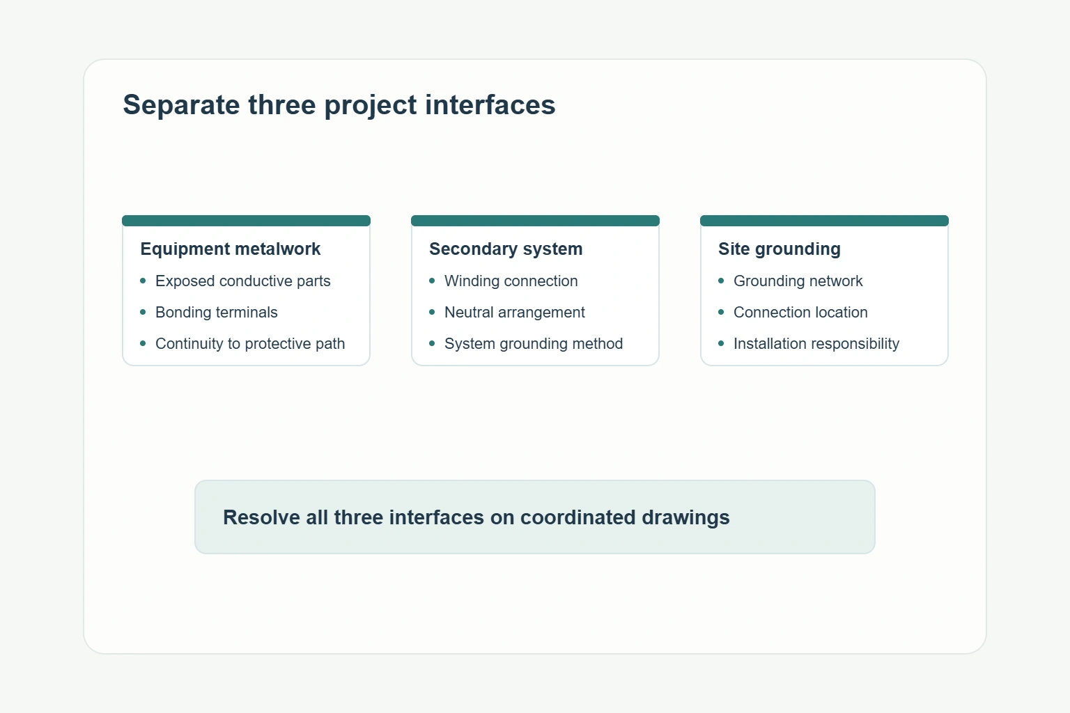
Transformer bonding and grounding describe different parts of an electrical design. Bonding connects conductive metal parts into an electrically continuous path; grounding connects a circuit or equipment to earth or an earth-connected reference. For a transformer project, identify the exact interface: the tank or enclosure, the winding neutral, or the site grounding network. Each needs a defined connection and an assigned scope of work. These distinctions follow the terminology in 29 CFR 1910.399.
A note saying “transformer grounding included” leaves several purchasing questions unanswered. Does the quotation include a terminal on the equipment, an internal bonding connection, a neutral connection, or field conductors? Replace that note with named connections and a drawing reference.
| Term | Meaning in the project | Question to resolve |
|---|---|---|
| Bonding | Electrical continuity between metallic parts. | Which parts are connected, by what arrangement, and within whose scope? |
| System grounding | The intentional earth connection of a system point. | Which point is connected, and what grounding method does the system design specify? |
| Grounded conductor | A circuit conductor intentionally connected to ground. | How is it identified on the single-line diagram and terminal drawing? |
| Equipment grounding conductor | A protective connection for non-current-carrying metalwork. | Where does the incoming connection terminate on the transformer? |
| Grounding electrode conductor | The connection to the grounding electrode. | Which drawing identifies its termination and installation responsibility? |
| Neutral terminal | The accessible connection to the winding neutral, when provided. | Is it brought out, identified, and included in the ordered configuration? |
The conductor distinctions above use US terminology. For a project using IEC documents, put the specified protective-conductor and earthing terms on the same interface schedule. Keep the drawing symbols and cable designations consistent across supplier and contractor documents.
Identify the connection points for the transformer tank or enclosure and the conductive parts covered by the equipment design. Ask for their locations on the arrangement drawing, their terminal details and whether the associated connections are factory-installed or completed on site.
Hammond Power Solutions explains bonding as providing a low-impedance return path to the source so that circuit protection can operate during a fault. That function makes electrical continuity a design requirement. A terminal marked with a grounding symbol still needs a specified connection and an inspection item in the project handover.
For example, a procurement interface schedule could require the manufacturer to identify the enclosure bonding terminal, the installer to connect the field protective conductor, and the commissioning team to verify the completed connection against the approved design. Assign each item explicitly rather than leaving all three under “grounding by others.”
Record the winding connection and whether a neutral terminal is required. The electrical designer then identifies the system grounding arrangement and the position of any system bonding connection. The transformer terminal drawing must agree with that decision.
Do not use a product photograph to resolve this interface. A visible stud on a tank says nothing about how the winding neutral is configured. Request the winding diagram and terminal schedule, with factory connections distinguished from field connections.
Show where the equipment connection meets the site’s grounding system and who supplies the conductors, connectors and installation work. The site drawing should identify the relevant electrode or grounding-grid reference, while the transformer drawing identifies the equipment terminal.
29 CFR 1910.304(g)(5) requires the grounding path from circuits, equipment and enclosures to remain permanent, continuous and effective. For procurement, translate that requirement into documented connections, accessible inspection points and responsibility for the completed installation.
“Separately derived system” has a specific meaning. Under 29 CFR 1910.399, it has no direct electrical connection to the supply conductors of another system, including through a solidly connected grounded conductor. Have the designer establish that status from the actual circuit arrangement before selecting the bonding detail.
An autotransformer deserves particular attention because its connection arrangement differs from a transformer with electrically separate primary and secondary windings. HPS’s three-phase autotransformer guidance describes a common H0/X0 neutral for its optional-neutral configuration and advises against locally grounding that point. The supplier’s guidance is specific to that product arrangement.
The purchasing consequence is straightforward: “three-phase transformer with neutral” is an incomplete specification. Attach the selected winding diagram and identify the upstream source, downstream loads and required neutral continuity. Ask the supplier to mark any deviation from that arrangement in the technical offer.
A grounding transformer is equipment used to provide a neutral connection for a system that needs one. HPS describes a zig-zag grounding transformer used to establish a neutral on a three-wire delta secondary. This is a different purchase from adding bonding terminals to a distribution transformer’s tank or enclosure.
If the project calls for that equipment, create a separate specification line. HPS’s grounding-transformer specification checklist asks for system voltage and insulation level, continuous neutral current, fault current and duration, impedance, connection type and environmental conditions.
Those inputs describe the electrical duty the equipment must meet. A request containing only a distribution-transformer kVA rating does not communicate that duty. Have the system designer supply the required values before seeking a grounding-transformer quotation.
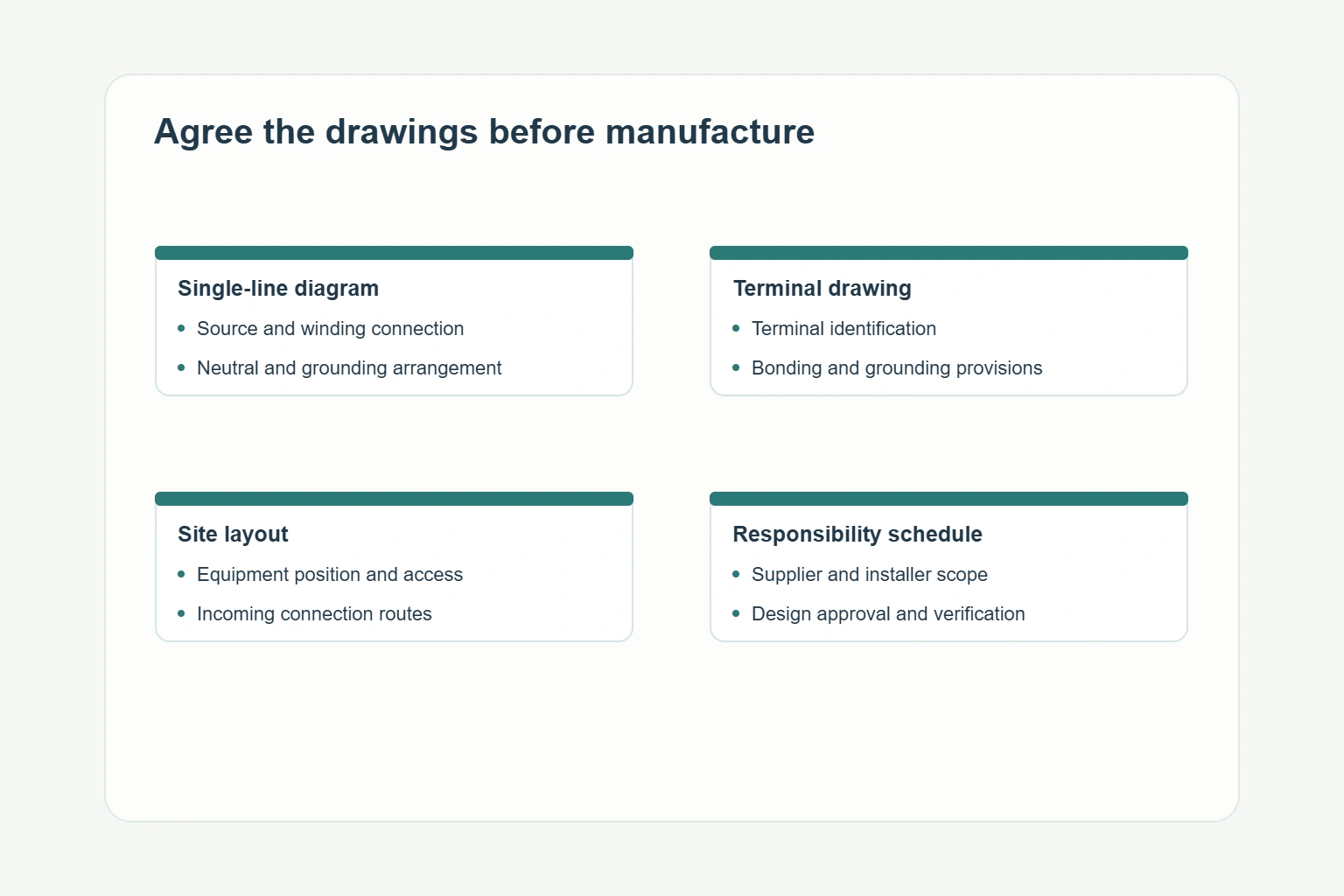
Build a small coordinated drawing set before the equipment order is released. Each document should answer a different question, with matching equipment tags and revision references.
| Document | Information it should settle | Review question |
|---|---|---|
| Single-line diagram | Sources, transformer connection, neutral arrangement, protection and system grounding method. | Does the offered transformer match the approved circuit? |
| Winding and terminal drawing | Terminal identifiers, accessible neutral, internal connections and field connection points. | Can the installer identify every required interface? |
| Equipment arrangement | Bonding terminals, cable approach, connection space and inspection access. | Can the specified conductors reach their terminals without an unresolved layout change? |
| Site grounding drawing | Connection to the site network and the relevant route or reference point. | Is the equipment-to-site boundary explicit? |
| Scope and inspection schedule | Factory work, field work, verification records and responsible parties. | Who supplies, installs and accepts each connection? |
Mark an unresolved interface as a technical query with an owner and a required response date. For example, if the single-line diagram calls for an accessible neutral but the supplier drawing omits it, resolve the mismatch before approving the drawing. Adding “confirm on site” postpones a decision that may affect the ordered equipment.
Record the answers in the technical offer or approved drawing package. Check that the purchase order references the same revision. A supplier clarification sent by email can otherwise be lost when drawings, installation instructions and the commercial scope are issued separately.
Consider a draft offer that says “grounding terminals supplied; installation by customer.” The buyer still needs to know which terminals are included, where they are located and which drawing controls their use. Return the offer with those three questions rather than accepting the note as a complete interface definition.
The revised submission should identify the equipment tag and drawing revision, label the terminals, distinguish factory connections from field work and list any excluded conductors or connectors. The project designer can then compare that submission with the system arrangement. Procurement can compare scope across bids without assuming that identical wording covers identical hardware.
Keep the same connection identifiers in the inspection schedule. If a terminal location changes during manufacture, update the arrangement drawing and the installation package together. That reduces the chance that an installer follows an earlier detail while the inspection team works from the revised one.
For handover, collect the approved terminal drawing, relevant installation instructions, agreed inspection records and the final list of outstanding items. Give any unresolved electrical connection a responsible owner and a closure requirement before energization. This makes the drawing review a practical control over equipment supply and installation, rather than a terminology exercise.
Bonding establishes electrical continuity between conductive parts. Grounding connects equipment or a system point to earth or an earth-connected reference. Identify both functions on the project drawings, with separate connection and scope details.
A metalwork terminal identifies an equipment connection point. The winding diagram and terminal schedule establish whether a neutral is available and how the approved system design uses it.
A grounding transformer has a specific neutral-provision duty. List it separately when the system design requires one, and provide the neutral-current, fault-duty and connection requirements.
Coordinate the single-line diagram, winding and terminal drawing, equipment arrangement, site grounding drawing, and scope/inspection schedule. Use matching equipment tags and revisions so each connection has a defined owner.
Start with the required equipment family in the HJD transformer catalog. If the project calls for a cast-resin distribution transformer, the SC(B)13 product page provides a starting point for discussing ratings and installation interfaces.
For a quotation, send the equipment tag, quantity, primary and secondary ratings, frequency, winding connection, site conditions and delivery destination. Attach the single-line diagram, the grounding-interface schedule and any required terminal or enclosure details through the HJD project inquiry contact. Identify the decisions already approved by the project engineer and the supplier information still needed to close the drawing review.