Request a Quote
Share your product list, technical ratings, quantity and delivery destination.
Review switchgear components, protection interfaces and drawings. Use a practical checklist to compare configurations and prepare a clearer RFQ.
When reviewing switchgear components, start with the power path: busbars, the switching device and cable connections. Then check the sensing, protection and control equipment, together with the earthing and access arrangements. These parts must work as a coordinated assembly; the exact list depends on the circuit and switchgear design.[1][2][3]
For procurement, the useful question is whether each feeder has a complete, documented configuration. Ask the supplier to connect the single-line diagram to a component schedule, identify interfaces and exclusions, and provide evidence for the proposed assembly. The quotation should show how the selected breaker fits the assembly and protection design.
Use the circuit duty to define the equipment: incoming supply, outgoing feeder, bus coupler or another function. Record the system voltage, required current, fault conditions and installation environment before comparing component lists.
This guide uses an illustrative medium-voltage breaker feeder. Other arrangements can combine functions differently. Eaton’s MEF guide, for example, describes both integral breaker protection and options using external relays.[1] A separate relay, voltage transformer or battery therefore should not be assumed from the word “switchgear.”
Keep the assembly standard on the enquiry. IEC 62271-200 covers a defined range of AC metal-enclosed assemblies above 1 kV and up to 52 kV; IEC 61439-2 covers low-voltage power switchgear and controlgear assemblies within its stated scope.[4][5] Apply the appropriate requirements to the selected equipment.
If the enclosure’s insulation arrangement is still undecided, the air-insulated vs. gas-insulated switchgear guide addresses that separate choice.
In the example below, the main power path runs from the busbar through a circuit breaker to the outgoing cable.
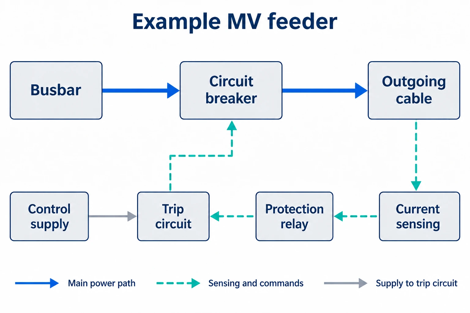
Current sensing provides an input to protection. A trip command then reaches the breaker through the specified actuation circuit. The auxiliary supply and operating-energy arrangement depend on the equipment selected.[1][2]
Use this functional view to organize the review. Actual connections, isolation points and component locations belong in the project drawings.
| Component group | Function to identify | What to request in the quotation |
|---|---|---|
| Busbars, joints and insulating supports | Main conductors and their insulation and support arrangement.[1] | Conductor specification, joint details, support arrangement and applicable current and withstand evidence. |
| Circuit breaker | Switching and interruption for the assigned circuit duty.[1] | Exact model, rated duties, operating mechanism, fixed or withdrawable arrangement, and supplied accessories. |
| Isolation and earthing devices | The means of isolating and earthing the relevant circuit.[3] | Isolation method, earthing point, operating conditions and interlock description. |
| CTs, VTs or sensors | Current and voltage inputs used by protection or metering.[2] | Required inputs, ratios or output characteristics, accuracy, burden where applicable, and connection details. |
| Protection and control equipment | Protection functions, commands and indications.[2] | Relay or trip-unit configuration, settings responsibility, control schematic and remote interfaces. |
| Auxiliary supply and trip components | Power and actuation provisions for the selected equipment.[1] | Supply type, voltage, source, included equipment and behavior following supply loss. |
| Cable terminations and earth bar | Cable interfaces and protective earthing connections.[1][2] | Cable entry, termination type, available space, support and bonding details. |
| Enclosure, partitions and interlocks | Separation, access boundaries and restrictions on operation.[3][4] | Compartment layout, access conditions, clearances and applicable assembly evidence. |
A component marked “optional” needs a decision: required and included, required but supplied elsewhere, or unnecessary for this circuit. Leaving that unresolved makes quotations difficult to compare.
Ask for the conductor, joint and support arrangement as a coordinated design. Where a proposal includes flexible links or insulated busbars, request their locations and connection details. Record what they connect, how they are supported and which configuration the supporting evidence covers.
Avoid approving a substitution on material or cross-section alone. Ask the assembly manufacturer to confirm the replacement, its interfaces and the evidence affected by the change. This is especially useful when a quotation lists a generic “copper busbar” without identifying the joint or support arrangement.
A current transformer (CT) or sensor must suit the protection input. ABB’s ZX2 catalogue specifically links CT selection to the protection device’s requirements.[2] Request the input specification and have the protection designer confirm compatibility. For a voltage transformer (VT), first establish which measurement or protection function needs its voltage signal.
Trace the trip command through the schematic to the breaker actuator. Then ask what powers each stage and what remains available after loss of the normal supply. Some configurations need external control power; Eaton documents an integral-protection option that does not.[1]
Where a battery and charger are specified, identify who supplies them, the loads they serve and the required duty. Do not add a generic battery allowance without those inputs.
Check the cable entry direction, termination interface and space against the actual cable information. Ask for a layout that shows how the cable reaches the termination, where it is supported and how the installation connects to the earth bar.
Keep earthing connections distinct from the switching arrangement used to earth a circuit. Review isolation, earthing and compartment access together with the interlock description.[2][3] Request the approved operating procedure that defines the site’s switching and access sequence.
Use one feeder identifier consistently across the single-line diagram, component schedule and detail drawings.
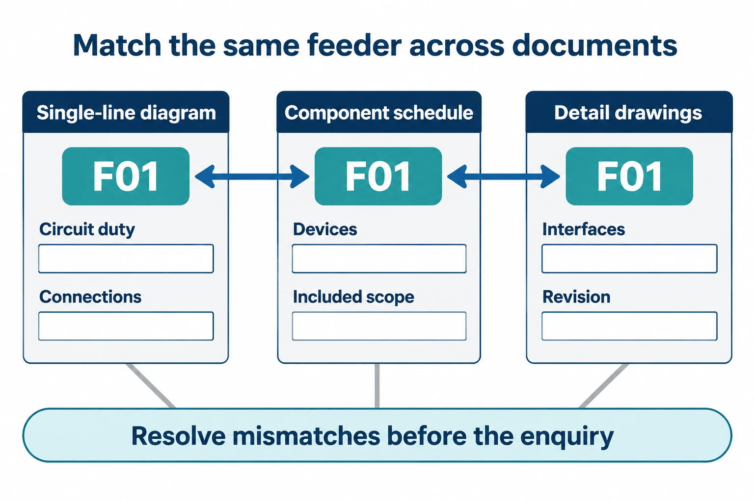
For example, suppose an outgoing feeder is tagged F01. Find F01 in the schedule, check the listed breaker and sensing equipment, then follow the drawing references to its protection, control and cable-interface details.
Ask the supplier to resolve a short set of questions:
Read symbols using the drawing’s legend. A single-line diagram needs companion detail drawings to explain terminal connections, interlocks and physical interfaces. Mark unresolved items against the feeder tag so they can be answered without searching through an unstructured email chain.
Keep component documentation and assembly evidence identifiable in the submittal. IEC 61439-1 sets general requirements for low-voltage assemblies and is used with the relevant assembly part.[6] Request the assembly verification documents as well as individual product data.
For an MV proposal, request the applicable assembly test evidence and the configuration it covers. The public scope of IEC 62271-200 identifies subjects including earthing circuits, interlocks and internal-arc testing.[4] Where a classification is required, ask for the corresponding report and installation conditions.
Compare the evidence with the offered configuration. A report for a different arrangement needs a documented explanation of applicability before it can support approval.
Send the single-line diagram with a feeder schedule. Include:
Ask the supplier to return a configuration schedule, drawing references and an explicit list of deviations. Mark missing inputs as open items instead of allowing an unstated assumption to become part of the order.
Use HJD’s project enquiry page to share the requirements available and request confirmation of the proposed scope. Attach drawings and the feeder schedule to the enquiry so the discussion can address specific circuits.
A circuit breaker is a switching device within a broader assembly. The assembly also includes the conductors, connections and other equipment needed for its particular function.[1] Review the complete scope when comparing offers.
No. The requirement depends on the protection, control and operating-energy design. Some integral-protection configurations operate without external control power.[1] Ask the supplier to show how the specified functions are powered.
Use both. The single-line diagram establishes circuit relationships; the component schedule identifies the proposed equipment. Link them by feeder tag, then check the detail drawings for wiring, access and installation interfaces.