Request a Quote
Share your product list, technical ratings, quantity and delivery destination.
Learn what a ring main unit does, how its ring ways and transformer protection work, and which ratings and site conditions to check before requesting a quote.
A ring main unit (RMU) is a compact assembly of medium-voltage switchgear used at a distribution-network connection point. A common three-way arrangement contains two load-break switches for the ring cables and a protected feeder for a transformer.[1] The ring ways connect the substation to the network; the transformer feeder supplies the local load through its selected protection arrangement.[2]
When selecting an RMU, start with the single-line diagram and the protection duty. “Three-way RMU” tells you how many circuit functions are present. It does not establish the required fault ratings, transformer protection or installation arrangement. Those belong in the specification before suppliers price the equipment.
A “way” is a circuit function, such as a ring connection or transformer feeder. In the common three-way arrangement, the two ring ways share a busbar; the protected branch supplies the transformer.[1]
The diagram below shows a circuit-breaker transformer feeder. Its relay sends a trip command to the breaker when the configured protection detects a fault.[4] The transformer is shown outside the RMU because it performs a separate job: changing the supply voltage.
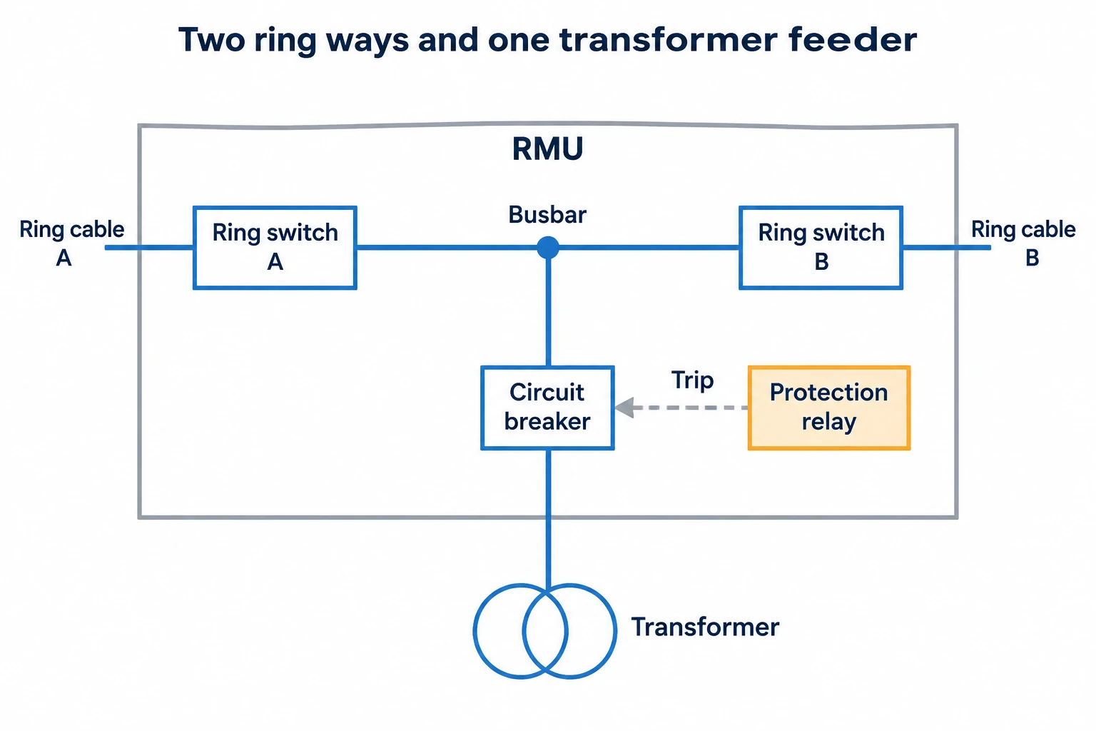
The functions to identify on a proposed drawing are:
Make the supplier’s single-line diagram part of the quotation. A front-view photograph can show the number of operating handles, but it cannot establish the complete protection arrangement or permitted access conditions.
A ring connection gives the substation two cable routes through the network.[2] The normal operating arrangement still matters. In the open-loop example described in Schneider Electric’s Electrical Installation Guide, one switching point remains open while the other ring switches are closed.[3]
If a cable section develops a fault, upstream protection may disconnect the affected feeder. Restoring supply involves identifying and isolating the faulty section, then reconfiguring the healthy network under the network operator’s approved procedure.[3] The alternative supply must also be suitable for the transferred load.
An RMU with two ring ways does not by itself provide automatic transfer. Remote restoration requires an appropriate control scheme, including the necessary fault indication, motor-operated switches, communications and auxiliary supply.[3] State whether the project needs local manual operation, remote control or a defined automation function, and identify who is responsible for the complete system.
The transformer feeder is where two otherwise similar RMU quotations may differ substantially.
For a switch-fuse option, request the approved combination and proposed fuse selection. Check their coordination with the transformer and surrounding protection.[1] Do not choose a fuse arrangement from transformer kVA alone.
A circuit-breaker feeder adds a protection chain that may include current transformers or sensors and a relay. Depending on the selected relay and settings, this can support coordination with other devices, accommodate transformer inrush and detect lower-level phase or earth faults.[4]
If the protection study requires adjustable relay functions, assess a circuit-breaker-and-relay feeder. If those functions are not required, a coordinated switch-fuse option can be assessed. Both options still need an engineering review of ratings, coordination and utility requirements.
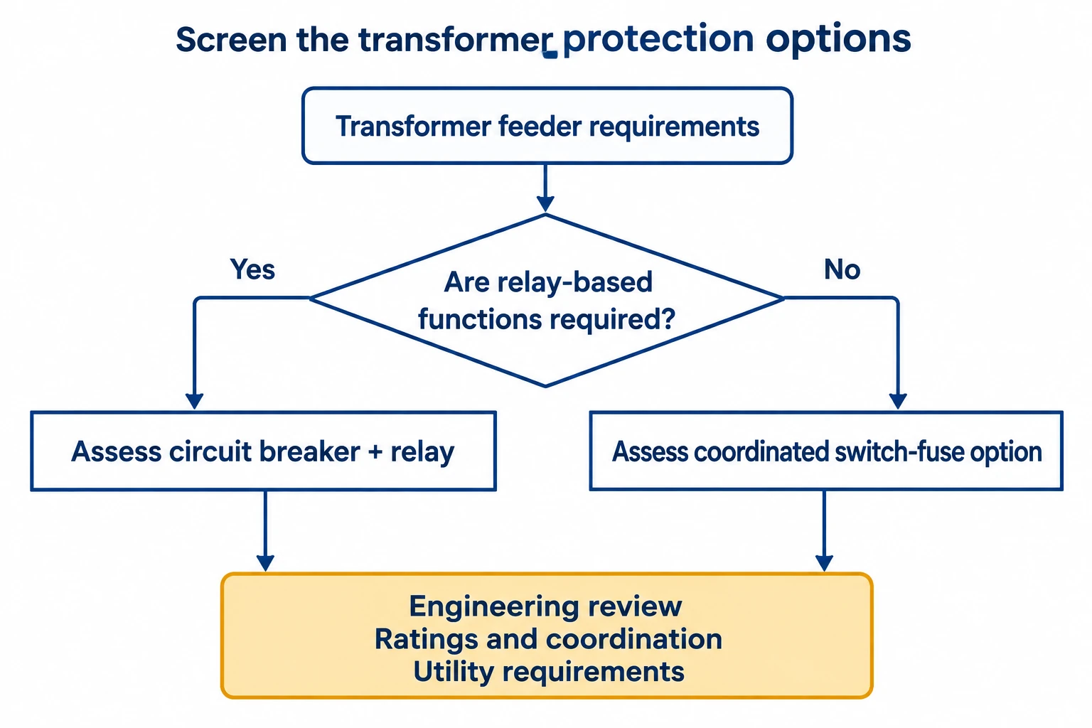
Ask the supplier to identify the protection components and the settings responsibility. “Circuit breaker included” leaves an important gap if the quotation does not explain how faults will be detected and how the trip circuit will operate. Where a self-powered relay is proposed, confirm its operating conditions and which other control functions need a separate supply.
An RMU specification may contain several current values. They describe different duties. ABB’s technical tables, for example, list normal current, short-time withstand current and its duration, peak withstand current, and circuit-breaker short-circuit breaking current separately.[9]
Compare each duty with its corresponding rating. A short-time withstand value alone does not establish the fault current that a switching device can interrupt.
Request a technical schedule identifying which ratings apply to the busbar, ring ways, transformer feeder and earthing circuit, with supporting test evidence for the offered configuration.[9]
RMUs are available with different insulation arrangements. Even gas-insulated designs do not all use the same gas: ABB’s SafeRing family includes both SF6-insulated and dry-air variants.[6] An insulation label alone is therefore insufficient for comparing complete units.
Ask for the service conditions of the exact model. Record the ambient temperature range, altitude, humidity and unusual exposure. Compare those conditions with the manufacturer’s declared limits and any required changes to the offered rating.[9]
Review the room or enclosure layout alongside the equipment drawing. Cable routing, equipment positions and operating access are part of substation planning.[8] For the offered RMU, request confirmation of cable entry, termination space, door and handle access, and the installation arrangement associated with any internal-arc classification. Specify outdoor service explicitly when required.
Maintenance access deserves its own question: what has to be de-energized to reach the compartment that needs attention? The loss-of-service-continuity classification, or LSC, describes which other compartments or functional units may remain energized when an accessible compartment is opened.[5] Ask the supplier to explain the classification against the actual compartment drawing and intended maintenance task.
For AC metal-enclosed switchgear, IEC 62271-200 is a relevant assembly standard within its stated scope.[7] Request the applicable edition and project requirements, plus the classification and test documents for the offered assembly. A general reference to IEC does not establish every rating or installation condition needed for your project.
Use the following worksheet to turn the network requirements into a comparable technical enquiry. Have the responsible engineer confirm the entries that depend on the network study and protection design.
| Information to provide | What the supplier should confirm |
|---|---|
| Network voltage, frequency and neutral-earthing arrangement | Offered equipment ratings and compatibility with the network requirements. |
| Single-line diagram and required circuit functions | Number and type of ring ways, transformer feeders, metering functions and spare ways. |
| Normal load and prospective fault duties | The matching ratings for each function, with withstand durations and breaking duties identified. |
| Transformer data and protection requirements | Switch-fuse or circuit-breaker arrangement, protection components, coordination inputs and settings responsibility. |
| Cable sizes, types and routing | Terminal interfaces, entry arrangement and installation space shown on the proposed drawing. |
| Site conditions and access requirements | Indoor or outdoor suitability, service-condition limits, compartment access and required installation provisions. |
| Control, monitoring and future-extension requirements | Included operating mechanisms, auxiliary supplies, interfaces and the supported extension arrangement. |
The single-line diagram, layout, protection approach and utility requirements should be aligned before the detailed specification is finalized.[8] For the transformer feeder, the transformer specification checklist can help organize the connected transformer’s input data.
Send the enquiry with a marked-up single-line diagram and site layout. Ask the supplier to return the proposed circuit configuration, technical schedule, protection scope and installation drawing, with deviations identified. This gives the technical reviewer something specific to accept or resolve before an order is placed.
An RMU is a particular compact arrangement of medium-voltage switchgear. “Switchgear” is the broader term and also covers other assemblies and circuit arrangements. Check the functional diagram when comparing products with different names.[1]
No. In an open-loop network, a fault may interrupt supply before the faulty section is isolated and the healthy network is reconfigured. Whether restoration is manual or automated depends on the installed protection, controls and network arrangement.[3]
No. RMU product ranges include alternatives. For example, ABB lists dry-air insulation in its SafeRing Air range alongside its SF6-insulated equipment.[6] Check the exact insulation medium, operating conditions and servicing requirements of the proposed model.
A sealed main compartment does not remove the need to check the inspection and maintenance scope for the complete installation. Protection chains require commissioning and periodic checks, while compartment access follows the equipment’s defined arrangements.[4][5] Request the model-specific maintenance instructions and responsibility schedule.