Request a Quote
Share your product list, technical ratings, quantity and delivery destination.
APPLICATIONS / SOLAR POWER
Step-up transformers, MV switchgear and auxiliary distribution for solar projects. HJD reviews the equipment package against your inverter data and connection requirements.
New solar plant / Additional generation / Equipment package
01 / THE SOLUTION
The inverter sets the low-voltage requirements. The collection network and grid connection set the medium-voltage side.
1
Use the inverter manufacturer’s transformer requirements to define winding arrangement, insulation, earthing and operating duty. The transformer low-voltage rating must match the inverter’s AC output.
HJD uses these requirements to review the transformer specification and the connection between the inverter and transformer.
2
The single-line diagram identifies feeder connections, isolation points and the grid interface. Added generation may require changes to the connection agreement, protection or export limit.
Specify switchgear voltage and fault duty, cable interfaces, metering and control signals against the approved project design.
3
A packaged station changes the transport load and foundation interface. Separate equipment leaves more installation and interconnection work at the site.
Set the package boundary before quotation, including auxiliary power, cables, controls and commissioning responsibilities.
02 / EQUIPMENT ARRANGEMENT
Define who connects, tests and delivers each part of the AC package.
SEPARATE EQUIPMENT
Procure the transformer and switchgear against the inverter and site design.
INTEGRATED STATION
Combine the specified AC equipment within an agreed station or skid arrangement.
The quotation should identify supplied equipment, external interfaces and work completed before shipment.
03 / EQUIPMENT & INTERFACES
Review these product families against the project specification. Solar inverter duty requires a configuration review.
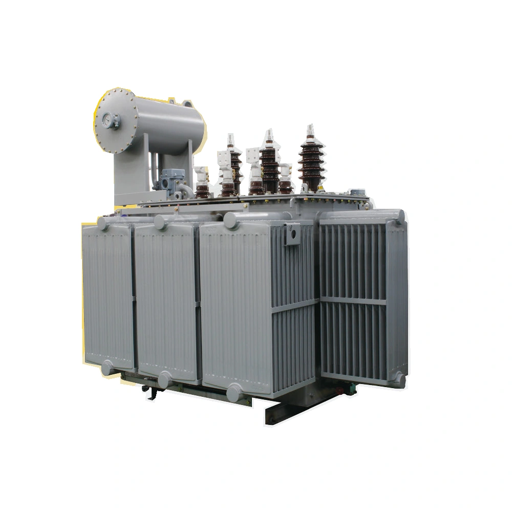
STEP-UP DUTY
Power transformer family
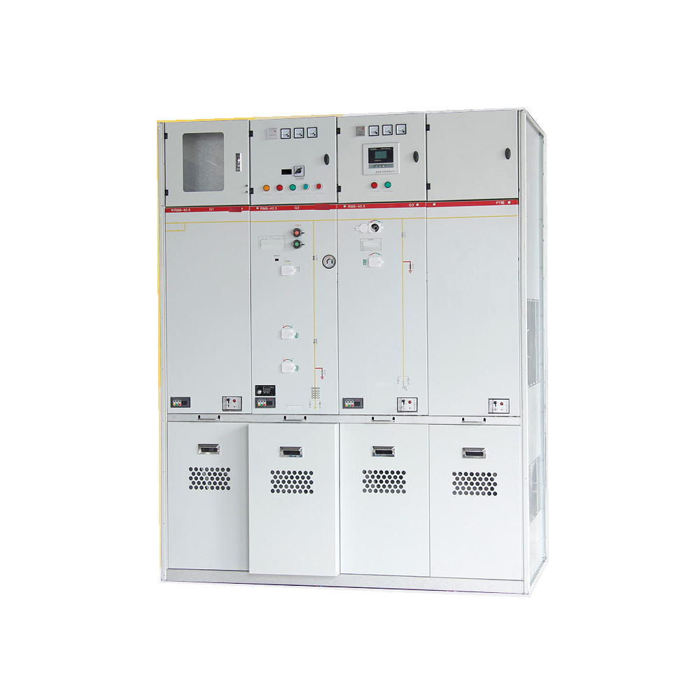
COLLECTION & GRID INTERFACE
DRM6-40.5 series
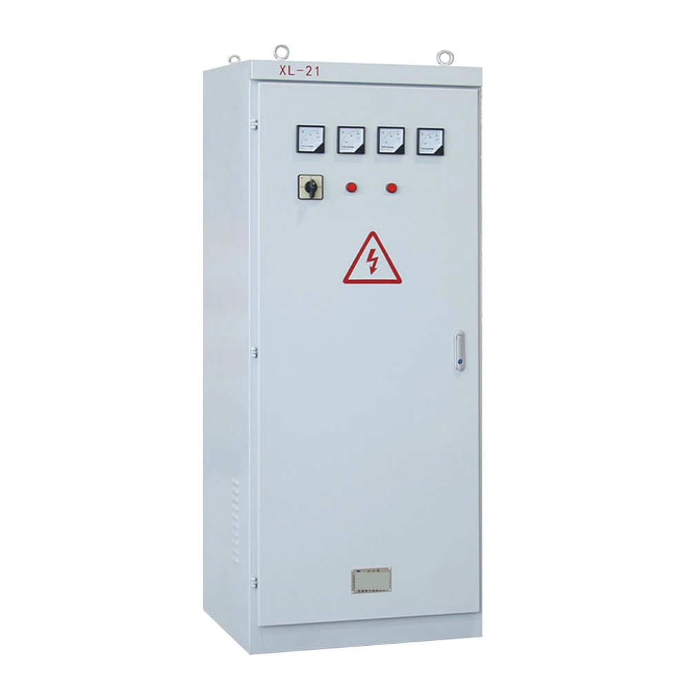
STATION AUXILIARY CIRCUITS
XL-21 distribution family
04 / FAQ
Answers for selecting the AC equipment between the inverter and the collection network.
In a medium-voltage solar plant, the step-up transformer connects the inverter’s AC output to the collection network voltage. Its specification must cover both voltage levels, generation capacity and the inverter’s operating requirements.
The plant single-line diagram determines the incoming and outgoing circuits, isolation and protection functions. Select the voltage class, current and fault ratings, cable interfaces, metering and controls for that arrangement. Requirements at the grid connection come from the network operator and project design.
Review it against the inverter manufacturer’s transformer specification first. Matching kVA and voltage alone leaves winding arrangement, insulation, earthing, impedance and thermal duty unresolved. The selected transformer configuration must meet those requirements.
Start with the inverter AC output and the required operating range, including reactive power. Review the transformer load curve, ambient conditions and specified cooling arrangement. The PV array’s DC rating alone does not define the required transformer capacity.
Separate equipment allows the project team to specify components around the site layout, while retaining responsibility for interconnections. An integrated station settles more interfaces within the package. Compare the supplied equipment, factory tests, transport dimensions and site work in each quotation.
The low-voltage side must match the inverter’s AC output. The medium-voltage side follows the collection network or agreed grid connection. Use the actual inverter model and project voltage requirements, then define the winding connections and tap arrangement.
Send your product list, technical ratings, quantity and delivery destination.
