Request a Quote
Share your product list, technical ratings, quantity and delivery destination.
Learn transformer sizing with single- and three-phase kVA formulas, checked examples, a load input table and an RFQ checklist for your project.
Transformer sizing starts with the load that will run at the same time, its voltage and phase, and the conditions the transformer must withstand. Calculate the required apparent power in kVA, then review starting duty, harmonics, installation conditions and planned additions before choosing a rating. The arithmetic establishes a capacity requirement; the application review determines whether a proposed transformer can serve it. [1][6]
For an RFQ, send the load schedule and calculation assumptions with the requested kVA. A supplier can then identify missing inputs and explain the basis of its offer.
Record each load separately before calculating a total. Keep measured operating demand, equipment nameplate data and estimated future demand in separate columns in your project worksheet. Their origins matter when someone reviews the calculation later.
The following template identifies the information to collect. Mark an unknown as unknown and assign someone to resolve it; a blank cell can otherwise become an unnoticed assumption.
| Input | What to record | Why it belongs in the RFQ |
|---|---|---|
| Supply and load voltage | Available input voltage; required output voltage; AC frequency | Defines the electrical conversion requested |
| Phase arrangement | Single-phase or three-phase; line-to-line voltage where applicable | Determines the calculation and connection requirements |
| Load demand | Electrical input kW and true power factor, or RMS current at a stated voltage | Provides the basis for calculated kVA |
| Operating schedule | Loads that run together; expected duration; standby and alternating loads | Makes the proposed concurrent demand traceable |
| Starting duty | Motor starting method, available starting-current data and acceptable voltage dip | Allows the supplier to review transient performance |
| Nonlinear loads | Drives, UPS systems, rectifiers and available harmonic data | Supports a review of transformer duty |
| Installation | Indoor or outdoor location, ambient range, altitude and ventilation constraints | Identifies conditions to compare with the offered design |
| Planned additions | Approved loads, operating sequence and expected installation date | Separates known expansion from a general contingency |
Use an operating scenario to document simultaneity. For example, identify which production equipment runs during the busiest shift and whether a standby unit can start while the main unit remains energized. Let the project engineer approve any demand or diversity assumption.
Future demand deserves the same detail. “Expansion allowance: 10 kVA for an approved packaging line” gives a reviewer something to verify. “Add some spare capacity” leaves the intended duty unresolved. Keep any additional contingency visible as a separate project decision.
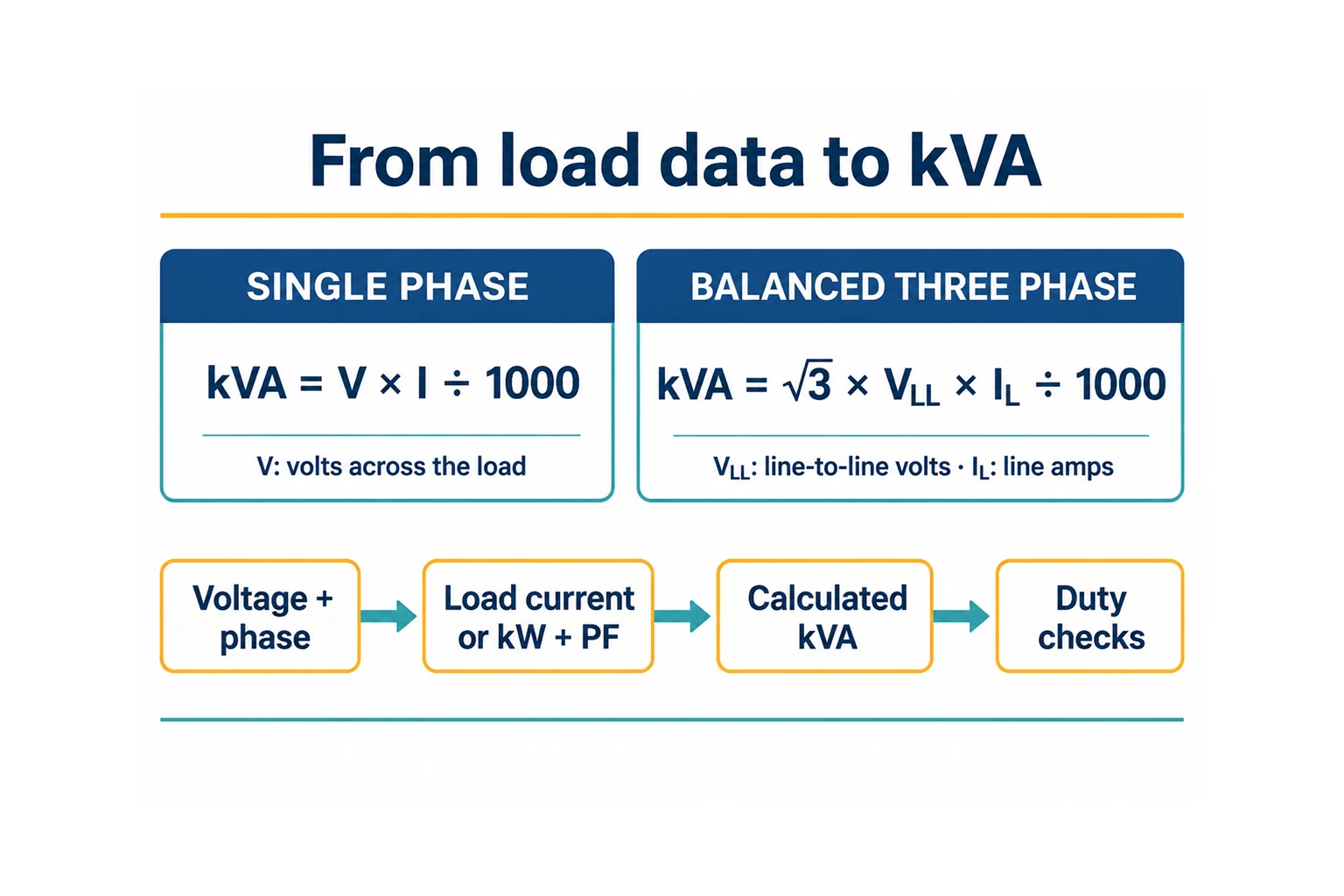
Use RMS voltage and current, with voltage measured across the load for a single-phase calculation. For balanced three-phase loading, use line-to-line voltage and line current. These conventions are essential to interpreting the ordinary apparent-power formulas. [1][3]
Single phase: kVA = V × I ÷ 1,000
Balanced three phase: kVA = √3 × VLL × IL ÷ 1,000
Here, VLL means line-to-line voltage and IL means line current. The three-phase expression assumes balanced operation; do not insert line-to-neutral voltage into its VLL field. [1]
A hypothetical single-phase load drawing 100 A at 240 V requires 24 kVA: 240 × 100 ÷ 1,000. For a three-phase application, first confirm that the load data and voltage reference match the balanced formula.
kVA = electrical input kW ÷ true power factor
Use power factor as a decimal. At a true power factor of 0.90, a 54 kW electrical input corresponds to 60 kVA. True power factor is the ratio of real power to apparent power and includes waveform distortion. Displacement power factor describes the fundamental voltage-current phase relationship; it can differ from true power factor for distorted waveforms. [2]
Ask what the reported value represents when a meter report or equipment sheet simply says “PF.” For a mixed load schedule, record the operating condition behind each value. Avoid assigning one convenient power factor to every device without an engineering basis.
Motor shaft output is mechanical power. Electrical input must also account for motor losses: input kW equals shaft output kW divided by efficiency at the applicable operating condition. Efficiency and power factor can change with load. [3]
At an assumed efficiency of 90%, 15 kW of shaft output requires approximately 16.67 kW of electrical input. At an assumed true power factor of 0.85, that input represents approximately 19.61 kVA. Use the motor’s documented efficiency and power factor for project calculations.
Consider a hypothetical balanced three-phase installation supplied at 480 V. Assume sinusoidal steady-state operation and a common lagging power factor. Its load schedule records 54 kW of concurrent electrical input at an aggregate true power factor of 0.90. An approved future addition will draw another 9 kW at the same power factor and operate concurrently with the existing load.
The calculation is:
The addition in this example depends on common power-factor assumptions, balanced operation and the stated concurrent schedule. For loads with differing operating characteristics, ask the engineer to establish the aggregate demand rather than copying this simplified sum.
The difference between 75 kVA and 70 kVA is 5 kVA. It is the remaining capacity in this hypothetical calculation, not proof that motor starting, harmonic heating or site conditions have been accommodated.
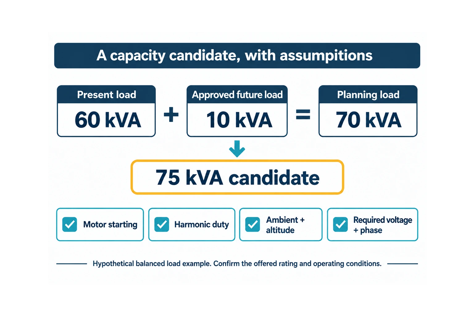
Record the candidate rating separately from the selected model. The RFQ should invite the supplier to confirm or revise the candidate and state why. If the approved load schedule changes, update the calculation before comparing quotations.
For balanced three-phase loading, rearrange the formula to obtain line current: I = kVA × 1,000 ÷ (√3 × VLL). For single phase, I = kVA × 1,000 ÷ V. [1]
These calculated examples use RMS quantities and the specified phase arrangement. Results are rounded to two decimals. They are arithmetic references, not measured transformer performance or conductor-sizing recommendations.
| Apparent power | Phase arrangement | Voltage used | Calculated current |
|---|---|---|---|
| 10 kVA | Single phase | 240 V across load | 41.67 A |
| 20 kVA | Single phase | 240 V across load | 83.33 A |
| 75 kVA | Balanced three phase | 480 V line-to-line | 90.21 A |
| 75 kVA | Balanced three phase | 208 V line-to-line | 208.18 A |
The two 75 kVA rows explain why a request for “75 kVA transformer amps” needs a voltage. They are separate calculations at specified voltages, not a full input-output performance model including losses.
A rating table also cannot establish physical dimensions. Request the proposed model’s drawing, mass, mounting details and ventilation requirements. Do not infer its footprint from kVA or use another manufacturer’s dimensions in a layout approval.
Running kVA does not describe motor starting. The review needs total operating load, the maximum starting event and the voltage dip the application can tolerate. Manufacturer guidance specifically identifies starting inrush and maintaining adequate output voltage as selection considerations. [4]
Send the starting sequence: which motor starts, what else is running and whether multiple starts can overlap. Ask the supplier to state the starting assumptions behind its recommendation. A quotation based only on running demand leaves that question open.
A schedule containing drives, UPS equipment or rectifiers needs a duty review alongside the kVA calculation. Manufacturer guidance distinguishes general-purpose, K-rated, harmonic-mitigating and drive-isolation designs as selection choices. [6]
Describe the equipment and provide available harmonic data. Do not specify a K-rating merely because the installation contains a drive, or assume that extra nameplate kVA alone resolves the duty. Request the supplier’s proposed design and its basis for the actual load profile. [4][6]
Compare the site’s conditions with the offered transformer’s documented rating conditions. For example, the HPS Millennium G VPI brochure identifies ambient and altitude conditions and associated derating; those limits belong to that product family. [5]
Give the supplier the site’s ambient range and altitude, plus the proposed enclosure or room arrangement. Ask it to confirm usable capacity under those conditions and identify any installation requirements. Keep that written confirmation with the selection record.
A buck-boost unit connected for a voltage adjustment requires the manufacturer’s application tables and selection procedure. Eaton’s guide selects the catalog number and quantity from the relevant line voltage, load voltage, phase, frequency and load data. [7]
The general load-kVA calculation above can describe demand, but it does not by itself select a buck-boost transformer’s nameplate rating. Identify this application explicitly in the RFQ and obtain a configuration-specific selection. See the step-up and step-down transformer guide for the broader voltage-conversion terminology.
Attach the completed schedule and identify its revision. Include supply voltage, required output voltage, frequency, phase arrangement, concurrent demand and the assumptions behind any future allowance. Add starting data, nonlinear-load information and site conditions where relevant.
Ask the supplier to return:
Use the transformer specification checklist to assemble the wider procurement package. For an HJD enquiry, send the load schedule and project requirements with your calculated kVA. Ask for configuration and availability confirmation in the quotation.
Divide electrical input kW by true power factor to calculate kVA. For example, 54 kW at 0.90 true power factor equals 60 kVA. Confirm that the kW figure is electrical input; a motor shaft-output rating needs an efficiency calculation first. Then review the application duty before choosing a rating. [2][3]
For balanced three-phase operation, 75 kVA corresponds to approximately 90.21 A at 480 V line-to-line, or 208.18 A at 208 V line-to-line. State voltage and phase whenever quoting the current. These are calculated apparent-power relationships; installation and protection design require separate review. [1]
Document concurrent demand, approved additions and any project contingency separately. Have the engineer and supplier review starting duty, harmonics and environmental conditions when choosing the candidate rating. Keep the resulting allowance and its purpose visible in the selection record.
A familiar kVA rating is a starting point for an enquiry. Ask the supplier to confirm the rating in the required voltage, frequency, phase arrangement, transformer type and installation configuration. Obtain the proposed model’s documentation before treating its dimensions, performance or availability as established.