Request a Quote
Share your product list, technical ratings, quantity and delivery destination.
Compare on-load and de-energized tap changers, then define the tapping schedule, control interfaces and evidence needed for a reviewable transformer enquiry.
A transformer tap changer changes the winding connection to adjust the transformer’s voltage ratio. An on-load tap changer (OLTC) can make that change while the transformer carries load; a de-energized tap changer (DETC) requires the transformer to be de-energized. The purchasing decision starts with the voltage range to be accommodated and whether service can be interrupted for a change. The enquiry then needs a tapping schedule, the required switching duty and a defined control package.
Describe the supply conditions before choosing a tap-changer acronym. Is the incoming voltage consistently above nominal, or does it vary enough during normal service to require repeated correction? Which bus must stay within the project’s permitted voltage band? Can the transformer be taken out of service for an adjustment?
Primary taps can accommodate a supply voltage that differs from the transformer’s nominal rating. Hammond Power Solutions’ explanation of primary voltage taps illustrates this relationship. A tapping percentage describes the specified winding arrangement; it is not a promise that every load will receive exactly that percentage more or less voltage. Read it with the nameplate voltages, tapped winding and supply conditions.
For procurement, distinguish an occasional setting change from an ongoing regulation requirement. That distinction affects the transformer arrangement, drive, controls, commissioning scope and maintenance provision. Record the expected variation and permissible interruption in the specification rather than asking a supplier to infer them from “voltage regulation required.”
| Question | De-energized tap changer | On-load tap changer |
|---|---|---|
| When can the ratio change? | With the transformer de-energized, under its specified isolation procedure. | During energized service within the equipment’s rated switching duty. |
| What equipment feature matters? | The selected winding connection and a mechanism suited to de-energized adjustment. | A switching arrangement designed to transfer between taps while carrying load. |
| What operating need should the buyer state? | Planned setting changes and acceptable outage arrangements. | Expected regulation duty, operating frequency and continuity requirements. |
| What else belongs in the enquiry? | Position indication, access, locking and any specified drive or interlock interfaces. | Drive, voltage regulator if required, measurements, indications, alarms and control interfaces. |
The boundary for a DETC is de-energization, not simply absence of load current. A transformer can remain energized with little or no connected load. The CAPT 099 manufacturer manual explicitly prohibits operating that de-energized tap changer while the transformer is energized. Specify the equipment and its operating restrictions; the project’s authorized personnel must establish the isolation procedure for the actual installation.
An OLTC performs a different switching task. Maschinenfabrik Reinhausen’s tap-changer technical guide describes arrangements that transfer load between adjacent taps while limiting circulating current through a transition resistor or reactor. This switching capability comes from the OLTC design. Adding a motor drive to a DETC does not turn it into an OLTC.
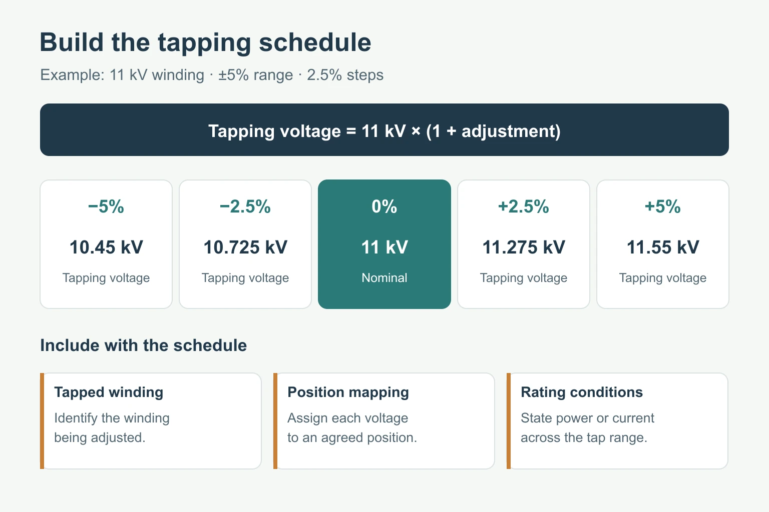
“Five taps” is incomplete. State which winding is tapped, its nominal voltage, the range, the increment and the service positions. Include the voltage assigned to each position and the rated power or current conditions that apply across the range. This makes offers comparable even when suppliers use different position numbering.
For example, a specified 11 kV winding with five equally spaced tapping voltages from −5% to +5% in 2.5% increments would have a schedule of 10.45, 10.725, 11, 11.275 and 11.55 kV. Use the approved nameplate and connection diagram to assign the actual position-to-voltage relationship.
A “raise” command also needs a defined meaning: raise which controlled voltage, measured at which point? Do not infer the output direction from a higher tap number alone. Agree the direction and indication conventions in the control drawings and test schedule. The transformer turns ratio guide explains why the winding connection and tap position must be identified when reviewing ratio results.
Multi-voltage reconnection and fine voltage trimming may serve different duties. If both are required, identify them separately on the winding diagram and ask which device performs each function. A list of voltage values does not, by itself, establish how or when the connections may be changed.
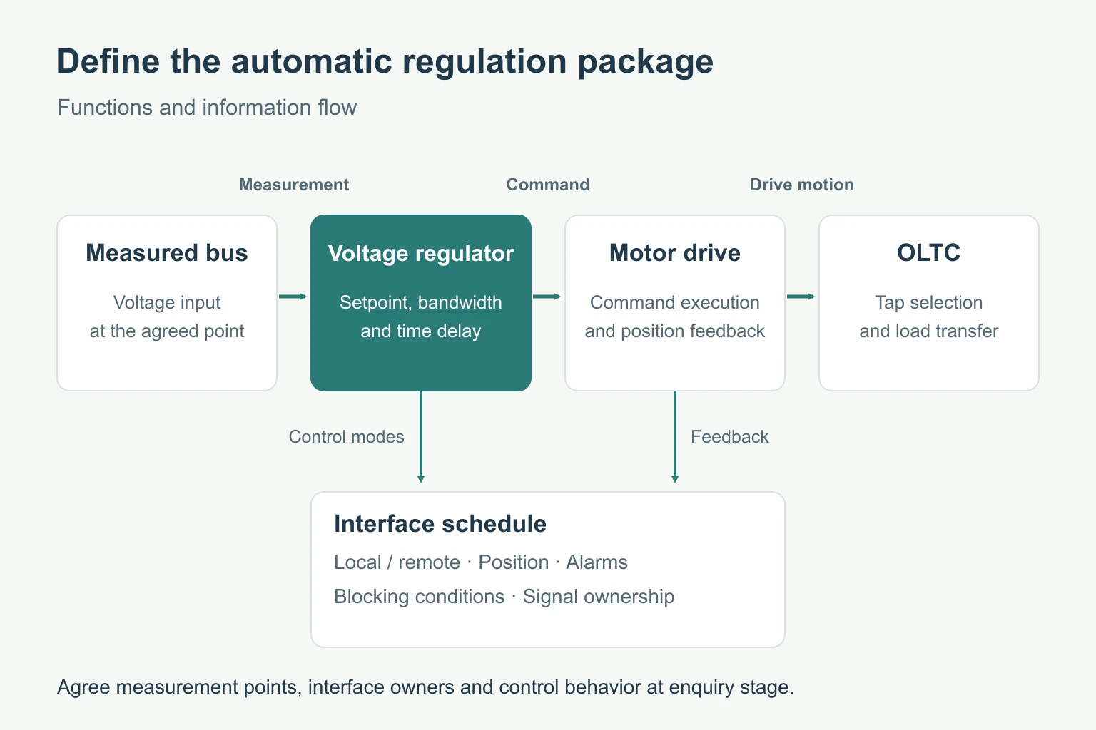
OLTC capability and automatic voltage control are separate specification items. For automatic operation, identify the controlled bus, measurement inputs, desired voltage and permitted deviation. Then define the drive supply, local and remote controls, position feedback, limits and alarm signals.
The TAPCON 250 operating instructions describe voltage regulation using a bandwidth and time delays, along with compensation and parallel-operation functions. The controls engineer should set the bandwidth, delay and parallel-operation functions for the project.
If transformers will operate in parallel, include that arrangement at enquiry stage. Request an agreed coordination method, the information exchanged between units and the behavior when communication or measurement is lost. Otherwise, “automatic tap changer” can conceal substantially different control packages.
Give each interface an owner. Identify who supplies the regulator, motor-drive wiring, voltage or current measurement, remote-control interface and commissioning support. Ask for a signal list that shows commands, indications, alarms and blocking conditions. This is more useful for bid review than a general claim of remote-control capability.
The tap changer must suit the associated winding, not just the transformer’s headline kVA or MVA. Reinhausen’s selection guidance calls for the winding connection, voltage and regulating range, service positions and insulation requirements; these support the assessment of through-current and step-voltage duty. Request the proposed device designation and the supplier’s selection data with the offer.
| RFQ field | Information to provide or request | What it resolves |
|---|---|---|
| Transformer arrangement | Rated power, winding voltages, frequency and connection. | Which winding and electrical duty the device serves. |
| Tapping schedule | Tapped winding, range, increments, position voltages and rating conditions. | Whether the offered adjustment matches the requirement. |
| Switching and insulation duty | OLTC or DETC, proposed ratings, insulation coordination and service conditions. | Compatibility with the transformer design. |
| Drive and controls | Supply, operating modes, regulator scope, feedback and interface list. | What is included and who completes the integration. |
| Operating environment | Installation conditions, insulating liquid where applicable and expected duty. | Suitability of the proposed construction. |
| Documents and acceptance | Nameplate schedule, diagrams, manuals and agreed inspection/test records. | What must be checked before release and acceptance. |
The public scope of IEC 60214-1:2014 covers performance requirements and test methods for both on-load and de-energized tap changers and their motor-drive mechanisms. Specify the applicable standard and edition in the purchase documents, together with the required evidence. A reference to a standard is not a substitute for identifying the offered model and its ratings.
No. When the specified device is a de-energized tap changer, removing load does not satisfy its operating requirement. Use the manufacturer’s defined equipment category and operating restrictions, and have the actual installation’s isolation arrangements established before any adjustment.
No. Load-switching capability and the voltage-control package are different parts of the specification. Confirm whether the offer includes the regulator, measurement inputs, drive, control modes and interfaces needed by the project.
No. Position numbering does not define the voltage effect. Check the tapped winding and the approved position-to-voltage schedule, then confirm the meaning of raise and lower in the control scheme.
No. The review also needs the winding arrangement, current and switching duty, insulation requirements, tapping schedule, mechanical interfaces and drive/control compatibility. Provide the existing transformer and tap-changer records rather than selecting a replacement from the voltage label alone.
Use the transformer specification checklist to bring the system data, tapping schedule and document requirements into one enquiry. Review the transformer product range, then contact HJD with the required adjustment duty and control scope so the offered transformer configuration can be discussed.