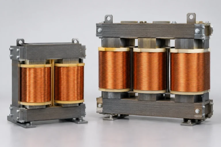
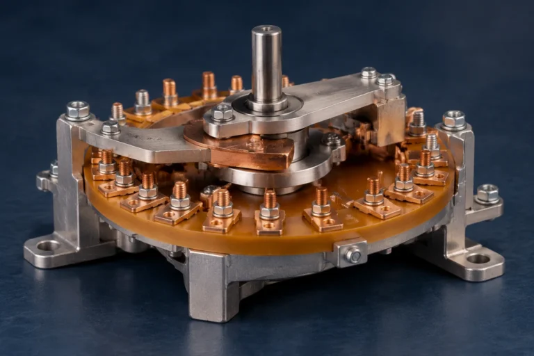
Request a Quote
Share your product list, technical ratings, quantity and delivery destination.
Learn how an autotransformer uses a shared winding and tap, where it is used, and what to check for isolation, voltage regulation and load ratings.
An autotransformer changes AC voltage through a winding shared by the supply and the load. A tap provides a different voltage across part of that winding. Because the two circuits have a conductive connection, the voltage change does not provide electrical isolation.[1]
Consider an autotransformer when the job is to match supply voltage to a load and a shared electrical connection is acceptable. If the application requires an isolation barrier, choose a design that provides one. If it requires a controlled output despite a varying supply, specify the voltage-regulation function as well; a fixed tap alone cannot do that.
In the single-phase step-down arrangement below, A and C are the ends of one continuous winding. B is a tap between them. The input spans the full winding, A–C, while the load is connected across B–C. The B–C section is therefore common to the input and output circuits; A–B is the series section.
The output uses part of the same winding and shares terminal C with the input.
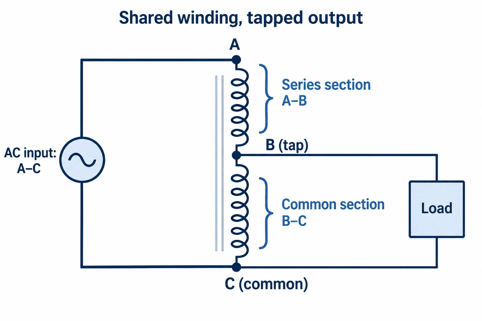
The AC supply produces changing magnetic flux in the core, inducing voltage along the winding.[1] The induced voltage per turn is approximately the same throughout the winding. In the ideal transformer model, the voltage ratio follows the ratio of the turns used:[2]
Vout / Vin ≈ Nout / Nin
Here, Nin is the number of turns across A–C and Nout is the number across B–C. Using fewer turns for the output gives a lower voltage in this arrangement. The approximation does not include winding losses or the voltage change under load, so the manufacturer’s rated output conditions still matter.
Power transfer includes both magnetic coupling and a direct electrical path between supply and load.[1] The tap changes the voltage relationship; it does not turn the common winding into two electrically separate circuits.
Obtain the selected transformer’s approved connection drawing before specifying its actual supply and load terminals.
A lower output voltage does not establish galvanic isolation. In an isolating transformer arrangement, power crosses between electrically separate windings through the magnetic field. In an autotransformer connection, a conductive path remains between the supply and output.[1]
That distinction should be resolved before comparing size or price. If electrical separation is a design requirement, a standard autotransformer connection cannot meet it. Ask the responsible engineer to define the required isolation function and the evidence needed for the selected equipment.
For a hypothetical procurement example, a machine may need a voltage different from the available supply. If the engineer has confirmed that the supply and load may remain electrically connected, an autotransformer can be considered. If the same project requires an electrically separate output, changing the tap or adding an enclosure does not provide that separation. The transformer arrangement must change.
Also distinguish a shared circuit terminal from a protective-earth connection. The common terminal C in the illustration is not labelled as neutral or earth. Its role in an actual installation depends on the supply system and approved design, which a generic principle diagram cannot establish.
A fixed-tap autotransformer has a fixed turns ratio. From the voltage-ratio relationship, a change in input voltage produces a proportional change in ideal output voltage. Selecting a tap can establish a suitable nominal output; it does not continuously correct supply variation.[2]
Variable transformers allow the output voltage to be adjusted. Staco’s variable-transformer range is one manufacturer example of this function.[4] An adjustable setting is useful when the operator needs to choose a voltage, but the presence of that setting alone does not establish automatic regulation.
Automatic voltage regulation adds a control function that responds to voltage variation. Staco separately describes a controlled variable-transformer topology for its automatic regulators.[5]
Use isolation and regulation requirements to screen a fixed-tap autotransformer before comparing ratings.
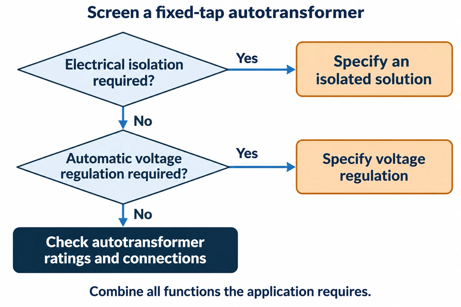
Write those requirements separately in the enquiry: the required voltage conversion, whether electrical isolation is needed, and whether the output must remain within a specified band. If regulation is required, also state the expected input range and load conditions. A supplier can then identify whether a fixed-ratio device, an adjustable device or a controlled system addresses the task.
Voltage matching is a practical application when isolation is unnecessary. Hammond Power Solutions describes autotransformers used to adjust a supply to suit load requirements and offers both step-up and step-down arrangements.[3] For procurement, confirm the permissible connection and ratings of the particular unit rather than assuming every product can simply be reversed.
Motor starting is a different duty. Motor-starting autotransformers are used in reduced-voltage starters to apply a temporarily reduced voltage during starting.[6] Treat the transformer as part of the starting system: provide the motor and load information, starting duration and starts per hour, and ask for the appropriate duty rating. A starting-duty designation alone does not establish suitability for continuous voltage conversion.
Adjustable AC supplies are another application. A variable transformer can provide an adjustable output within its specified range.[4] Ask separately about output-current limits, the adjustment method and isolation. The ability to turn a control or move between settings does not resolve those other requirements.
The shared winding can reduce the winding material required compared with a corresponding two-winding transformer. The advantage becomes more significant when the input and output voltages are close; the IIT Madras treatment of autotransformers relates this to the turns ratio and winding-current relationships.[2]
This explains why an autotransformer may be worth evaluating for a modest voltage change. It does not establish a fixed saving in price, mass or losses for a quoted product. Compare those quantities using the offered configuration and the same operating requirements.
Ask for the usable output rating in the proposed connection. Keep the complete autotransformer output rating distinct from a winding or component rating, and request clarification if a quotation uses “transformer kVA” without defining its basis. Include the load current and duty in the review; a voltage ratio by itself does not establish how much load the equipment can supply.
The transformer quote comparison guide can help align the equipment scope and delivery responsibilities before comparing prices.
Start with the load’s requirements and the available supply. The transformer specification checklist provides a broader RFQ structure. For an autotransformer, make the following points explicit. Use the autotransformer and two-winding comparison if the isolation requirement is still unresolved.
| Information to provide | What to confirm with the supplier |
|---|---|
| Supply and required output | Input range, nominal output, phases, frequency and permitted voltage variation |
| Load and operating duty | Continuous output rating, load current, starting behaviour and duration of intermittent duties |
| Isolation requirement | Whether the project permits a conductive connection between supply and load |
| Adjustment or regulation | Fixed taps, an adjustable setting, or automatic correction within a specified operating range |
| System connections | Line-to-line and line-to-neutral requirements, available terminals and the approved connection diagram |
| Installation conditions | Ambient conditions, altitude, enclosure, cooling clearances and mounting arrangement |
| Acceptance documents | Configuration-specific ratings, drawings, operating limitations and the agreed test records |
Do not infer a neutral connection from the word “autotransformer.” HPS, for example, describes optional neutral terminals for the three-phase designs covered by its guidance.[7] If the load needs a neutral, have the supplier identify the required configuration and have the project engineer review the complete system connections.
Request the connection drawing and rating schedule with the offer. They should describe the same model, tap arrangement and duty. Where an offer relies on an alternative configuration, keep that difference visible until engineering has accepted it.
Autotransformers can be designed for either function.[3] Use the manufacturer’s permitted connection and rating for the selected unit. Do not infer that an arbitrary unit may be reverse-connected at the same rating solely from a generic winding diagram.
Changing the output setting does not remove the conductive connection in an autotransformer. If isolation is required, confirm that the complete supply includes an appropriate electrically separate arrangement; the adjustable autotransformer by itself does not provide it.[1]
No such role is assigned by the principle diagram. Confirm it from the actual system and manufacturer drawings. In particular, neutral-terminal availability can depend on the product configuration, as illustrated by HPS’s guidance for its three-phase units.[7]
Do not assume this from its name. Motor-starting autotransformers serve a temporary reduced-voltage starting duty.[6] Request an explicit continuous-duty rating for the proposed connection and load before considering that use.